Viking VBCV42381 Installation Instructions - Page 4
Custom Hood Canopy Cutouts
 |
View all Viking VBCV42381 manuals
Add to My Manuals
Save this manual to your list of manuals |
Page 4 highlights
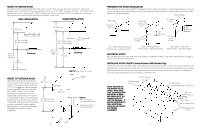
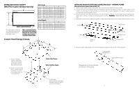
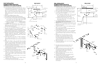
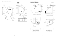
INSTALLING HOOD CANOPY (VBCV/VICV Custom Ventilator Kits Only) A* B* Bottom Cutout Dimensions *For best results, center the unit over the burners of the cooking product (front to back; right to left). Make sure the back wall of the custom hood canopy is flush with the cutout so the ventilator system may be mounted as shown below. Wall Hoods A 30" W. 27 7/16" (69.7 cm) 36" W. 33 7/16" (84.9 cm) 42" W. 39 7/16" (100.2 cm) 48" W. 45 7/16" (115.4 cm) 54" W. 51 7/16" (130.7 cm) 60" W. 57 7/16" (145.9 cm) 66" W. 63 7/16" (161.1 cm) Island Hoods A 36" W. 33 7/16" (84.9 cm) 42" W. 39 7/16" (100.2 cm) 54" W. 51 7/16" (130.7 cm) 66" W. 63 7/16" (161.1 cm) B 21 7/16" (54.5 cm) 21 7/16" (54.5 cm) 21 7/16" (54.5 cm) 21 7/16" (54.5 cm) 21 7/16" (54.5 cm) 21 7/16" (54.5 cm) 21 7/16" (54.5 cm) B 27 9/16" (70.0 cm) 27 9/16" (70.0 cm) 27 9/16" (70.0 cm) 27 9/16" (70.0 cm) Custom Hood Canopy Cutouts A B 1) Position ventilator system inside of the custom hood canopy and center it front to back and left to right. 2) Bottom mounting holes fasten ventilator system to bottom of custom hood canopy with the screws provided Custom Hood Canopy Built-in Ventilator System 3) OPTIONAL Rear mounting holes fasten ventilator system to rear of custom hood canopy. 6 INSTALLING ROUGH-IN PLATE AND CONNECTING DUCT - INTERNAL POWER (Also see instructions supplied with ventilator kit) 1. Attach rough-in plate to studs in the inside, top of hood with four (4) #10-24 nuts provided. 2. Connect ductwork using supplied transition and damper (transition and damper are part of rough-in plate on some models). Use duct tape to make all joints secure and air tight. In some installations, it is easier to attach transition to plate before attaching plate to hood. 3. Remove wire box cover. Remove a knockout from the wiring box. Feed 6" of power cable through opening and attach cable to wiring in wiring box with appropriate connector. WARNING: MAKE SURE ELECTRICAL SUPPLY IS OFF. 4. Wire black to black, white to white, and green or bare wire beneath green ground screw. Replace wire box cover. Studs Top of Hood Nuts Rough-in Plate Studs Wire box cover Nuts 5. Plug the rough-in plate power cord into the receptacle located on the top side of the light panel. 3-prong power supply plug-in 2-prong blower plug-in Receptacles are located behind and above control panel. 7
-
 1
1 -
 2
2 -
 3
3 -
 4
4 -
 5
5 -
 6
6 -
 7
7 -
 8
8 -
 9
9 -
 10
10 -
11
-
12
 |
 |
