Viking VDD5360 Installation Instructions - Page 4
Plan The Wiring, Prepare The Downdraft, Plan Cabinet Cutouts
 |
View all Viking VDD5360 manuals
Add to My Manuals
Save this manual to your list of manuals |
Page 4 highlights
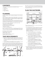
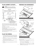
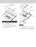
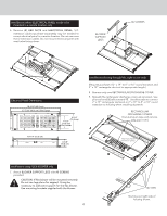
PLAN CABINET CUTOUTS PREPARE THE DOWNDRAFT CAUTION: BEFORE CUTTING HOLE IN CABINET FOR DUCTWORK, check for interference with floor joists, wall studs, electrical wiring, or plumbing. INSTALLATION CENTER LINE 6 7/8" 19¼" FLUSH HOLE FOR 2" X 19¼" DUCT INSIDE CABINET BACK 26¾" 19¼" centered 2" 6" * 6" * 2" INSIDE CABINET FLOOR 1½" HOLE FOR 8" or 10" ROUND DUCT (*Adjustable 6" Left and 6" Right) (When using Remote Discharge Plate - Hole is adjustable 6" Left and 6" Right from Installation Center Line.) Use the dimensions in the above illustration to help plan how and where to provide duct access through your cabinet. Generally, 1-7/8" x 19" rectangular duct will be used through left, right, and back of cabinet - while 8" round duct will be used through cabinet floor. For left, right, or rear exhaust: Allow at least 18" for transition and elbow or blower. For left/right exhaust: A 30" deep cabinet is recommended to align properly with flex blower. Flex blower can be mounted to rear cabinet wall or to a platform/frame (not provided) on the base of the cabinet floor. (See flex blower instructions). Cabinet depths of 24" to 30" are required - depending on the type of cooking appliance. FRONT PANEL COVER CLAMP CHANNEL (4-6) HEX NUTS Electrical panel can be mounted remotely. Installations ducting through front panel opening only: 1. Place the downdraft on its back on a table or flat work surface. 2. Loosen the HEX NUTS on the CLAMP CHANNEL and remove the FRONT PANEL COVER. COVER PLATE FLEX BLOWER COVER PLATES (included with blower) FRONT PANEL LOWER CHANNEL PLAN THE WIRING 1. This downdraft blower using the Flex Blower (purchase separately) draws 3.0 Amps and requires a 120 VAC, 60 Hz circuit. If using a remote blower (purchase separately), the system draws 6.0 Amps (max.) and requires a 120 VAC, 60 Hz circuit. 2. The unit has a 18 in. long power cord with a 3-pronged plug. Plan to provide a grounded outlet in a location which will allow the unit's power cord to reach. 3. Install electrical box according to local codes. 4. The length of cable from the electrical box to the downdraft is 20 in. 5. The length of blower (sold separately) cable to the electrical box is 5 ft. If blower discharge is down, electrical panel must be relocated. See Step 6. Installations using FLEX BLOWER only: (Purchase Model VDVI600 Flex Blower separately.) Note: Remove adapter plate from Flex Blower per instructions packed with blower. 3. Determine its location on FRONT PANEL and whether it will discharge to the left, right, or down. Use a combination of COVER PLATES (3" and/or 6" wide) to close the opening on side(s) of blower. Slide the blower and cover plates between the LOWER 4 CHANNEL and the clamp channel. Tighten the hex nuts to secure blower and panels in place.
-
 1
1 -
 2
2 -
 3
3 -
 4
4 -
 5
5 -
 6
6 -
 7
7 -
 8
8 -
 9
9 -
 10
10 -
11
-
12
 |
 |
