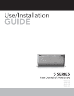
Viking VDD5360 Installation Instructions - Page 5
Remote Discharge Plate, Front Panel, Cover Plates, Lower Channel, Upper Support Brackets, Slide
 |
View all Viking VDD5360 manuals
Add to My Manuals
Save this manual to your list of manuals |
Page 5 highlights
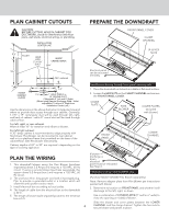
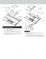
COVER PLATE 8" OR 10" ROUND REMOTE DISCHARGE PLATE (Purchase Separatly) COVER PLATES FRONT PANEL LOWER CHANNEL SLIDE CHANNEL UPPER SUPPORT BRACKET Flex Blower shown installed. Installations using FLEX BLOWER (in remote location) or REMOTE BLOWER only: 4. Use the REMOTE DISCHARGE PLATE and determine its location on FRONT PANEL. Use a combination of COVER PLATES (3" and/or 6" wide) to close the opening on side(s) of remote discharge plate. Slide the remote cover plate and cover plates between the LOWER CHANNEL and the clamp channel. Tighten the hex nuts to secure the plates in place. LONG OR SHORT SUPPORT LEGS HEX SCREW All Installations: 5. Slide UPPER SUPPORT BRACKETS into SLIDE CHANNEL at top left and right of unit. Attach LONG OR SHORT SUPPORT LEGS (depending upon cabinet height) to bottom sides of unit with HEX SCREWS provided. Do not tighten hex screws completely at this time. 5
-
 1
1 -
 2
2 -
 3
3 -
 4
4 -
 5
5 -
 6
6 -
 7
7 -
 8
8 -
 9
9 -
 10
10 -
 11
11 -
12
 |
 |
