Viking VDD5360 Installation Instructions - Page 8
Install Electrical Wiring, Install Ductwork
 |
View all Viking VDD5360 manuals
Add to My Manuals
Save this manual to your list of manuals |
Page 8 highlights
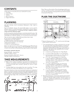
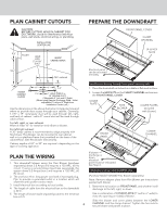
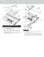
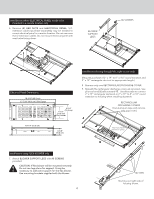
INSTALL DUCTWORK CAUTION: Before cutting hole in cabinet for ductwork, check for interference with floor joists, wall studs, electrical wiring, or plumbing. 1. Cut hole in cabinet as well as holes in wall or floor as necessary. 2. Mount the roof or wall cap and work back towards the cabinet, attaching all ductwork, elbows and transitions as previously planned. Tape all ductwork connections to make them secure and air tight. 3. Connect ductwork (and transition, if required) to downdraft. Installations using REMOTE BLOWER only: CAUTION: All electrical wiring should be done by a qualified person(s) in accordance with all applicable codes and standards. 1. Mount a standard wiring box, with 3-pronged receptacle, within reach of the downdraft's power cord. 2. Run appropriate power cable into cabinet and connect it to electrical box and receptacle. 3. These exterior or in-line blower can be used: Models VDVE900, VDVE1200 - Exterior 120 VAC • 60 Hz • 6.0 A (max.) INSTALL ELECTRICAL WIRING Installations using FLEX BLOWER only: CAUTION: All electrical wiring should be done by a qualified person(s) in accordance with all applicable codes and standards. 1. Mount a standard wiring box, with 3-pronged receptacle, within reach of the downdraft's power cord. 2. Run appropriate power cable and connect it to receptacle. 3. Connect blower wires to wires in wiring box. Black to black, white to white, blue to blue, orange to orange, gray to red, and green to ground screw. 4. Replace wiring box cover. WIRING BOX COVER 4. Run 2-wire plus ground power cable from the exterior or inline blower to wiring box on adaptor plate. Remove WIRING BOX COVER. RECEPTACLE 5. Connect blower wires to power cable from exterior or in-line blower. Black to black, white to white, and green to ground screw. CABINET BOTTOM ELECTRICAL PANEL CABLE 6. Replace wiring box cover. 7. Plug ELECTRICAL PANEL CABLE into RECEPTACLE at bottom/right of downdraft housing. 5. Plug ELECTRICAL PANEL CABLE into RECEPTACLE at bottom/right of downdraft housing. 8. Plug the downdraft's power cord into the outlet. Make sure that the power cord is routed away from the heat generated by the cooktop. 6. Plug the downdraft's power cord into the outlet. Make sure that the power cord is routed away from the heat generated by the cooktop. 8
-
 1
1 -
2
-
 3
3 -
 4
4 -
 5
5 -
 6
6 -
 7
7 -
 8
8 -
 9
9 -
 10
10 -
 11
11 -
 12
12
 |
 |
