Viking VDD5360 Installation Instructions - Page 6
Installations using FLEX BLOWER only
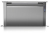 |
View all Viking VDD5360 manuals
Add to My Manuals
Save this manual to your list of manuals |
Page 6 highlights
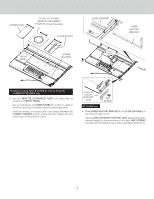
Installations where ELECTRICAL PANEL needs to be mounted in a remote location only: 6. Remove (4) HEX NUTS and ELECTRICAL PANEL. 5-ft. extension cables (purchase separately) may be needed to mount electrical panel in a remote location. Do not use more that 2 extension cables. Do not mount electrical panel with vent holes facing down. BLOWER SUPPORT LEGS (4) SCREWS Electrical Panel Dimensions 18-3/16" (46.2 cm) 17-7/16" (44.3 cm) Slot Center 16-1/4" (15.9 cm) 6-1/4" (15.9 cm) 4-1/2" (11.4 cm) Slot Center Installations ducting through left, right or rear only: (Requires purchase of 2" x 19" to 8" or 10" round transition and 2" x 19" rectangular duct cut to appropriate length.) 8. Remove only one RECTANGULAR DISCHARGE COVER. 9. Beneath the rectangular discharge cover just removed - Use pliers to bend (6) tabs outward 90 . Use these tabs to connect 2" x 19" rectangular ductwork or 2" x 19" to 8" or 10" round transition to housing when installing ductwork. RECTANGULAR DISCHARGE COVERS (Cut aluminum tape and remove only one cover.) 6-5/8" (16.8 cm) This Front Panel remains in place. Installations using FLEX BLOWER only: 7. Attach BLOWER SUPPORT LEGS with (4) SCREWS provided. CAUTION: If flex blower will be mounted remotely: Do not use legs alone for support. It may be necessary to add extra support for the flex blower. Use mounting brackets supplied with the blower. 6 (6) TABS Ducting out right side of housing shown.
-
 1
1 -
 2
2 -
 3
3 -
 4
4 -
 5
5 -
 6
6 -
 7
7 -
 8
8 -
 9
9 -
 10
10 -
 11
11 -
 12
12
 |
 |
