Viking VWH4878TSS Installation Instructions - Page 19
Planning Information - direct
 |
View all Viking VWH4878TSS manuals
Add to My Manuals
Save this manual to your list of manuals |
Page 19 highlights
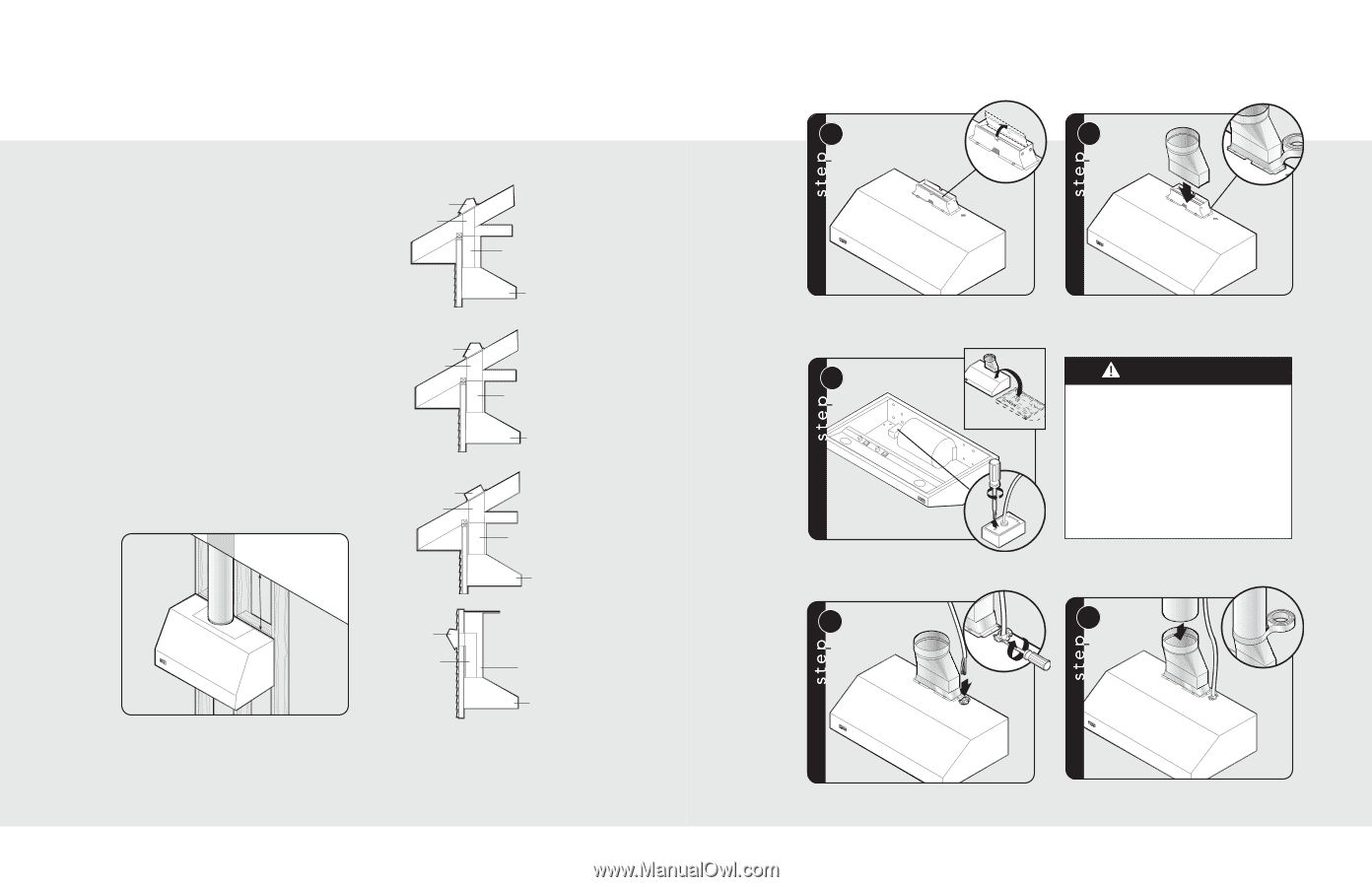
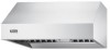
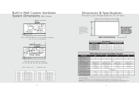
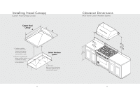
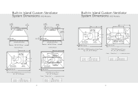
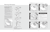
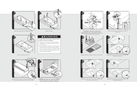
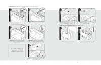
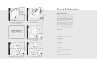
Planning Information Proper installation of ducting is extremely important to ensure maximum performance from any ventilation product. • All CFMs are based on tests at 0.1 static pressure: without applying static pressure, CFM would be greatly overstated. • Straight runs and gradual turns are best; for example, each 90º elbow is equivalent to 5-10 feet (1.52-3.05 cm) of straight run. • Never use flexible duct; it creates back pressure/air turbulence and greatly reduces performance. • Proper performance is dependent on proper ducting; make sure that a qualified and trained installer is used. • Check with a qualified and trained installer or local codes for makeup air requirement, if any. • Max. amp rating for hoods includes recommended ventilator kit rating; all products must be hard wired direct with 2-wire with ground. Plan where the duct work will be located. Install proper-sized duct work, and roof or wall cap for the type of blower you are using. Recommended hood locations for the most common installations are shown. Adjust your measurements for various heights of ceilings, soffits, cabinets, or ranges/rangetops. Check Framing Roof cap 7" round duct Roof cap 10" round duct Exterior blower 10" round duct 300 or 600 CFM single blower interior-power typical ductwork Duct cover or soffit Hood 1200 CFM single blower interior power typical ductwork Duct cover or soffit Hood 900, 1200, or 1500 CFM exterior power typical ductwork Duct cover or soffit Hood Wall cap Duct Wall Installation exterior power typical ductwork Duct cover or soffit NOTE: Because of the weight of the hood make sure that the mounting screws are driven into the framing and not just the drywall. It may be necessary to drill additional holes in the canopy for proper alignment. Hood NOTE: Wall exhaust must be a minimum of 24" (61.0 cm) from ground. This may vary depending on local codes and geographic location. Electrical Supply Run 120 VAC electrical wiring from service panel to installation location. See Specifications pages for the maximum amp requirements. 36 Installation (VWH 10"H. Wall Hoods w/Standard Ventilator) 1 2 4 5/16" nut driver Check damper for unrestricted movement, adjust if necessary. 3 Flip hood over and remove electrical box cover. Attach transition to damper. Seal with aluminum tape. WARNING To reduce the risk of fire, electric shock, or injury to persons, observe the following: • Use this unit only in the manner intended by the manufacturer. If you have any questions, contact the manufacturer. • Before servicing or cleaning unit, switch power off at service panel and lock service panel to prevent power from being switched on accidentally. When the service disconnecting means cannot be locked, securely fasten a prominent warning device, such as a tag, to the service panel. 4 5 1 2 1 Insert 6" of electrical wiring through the top of vent hood and secure using wiring restrain. Refer to local codes. Slide duct over transition and tape around joint. 37
-
 1
1 -
2
-
3
-
4
-
5
-
6
-
7
-
8
-
9
-
10
-
11
-
12
-
13
-
 14
14 -
 15
15 -
 16
16 -
 17
17 -
 18
18 -
 19
19 -
 20
20 -
 21
21 -
 22
22 -
 23
23 -
 24
24
 |
 |