Viking VWH4878TSS Installation Instructions - Page 21
Warning
 |
View all Viking VWH4878TSS manuals
Add to My Manuals
Save this manual to your list of manuals |
Page 21 highlights
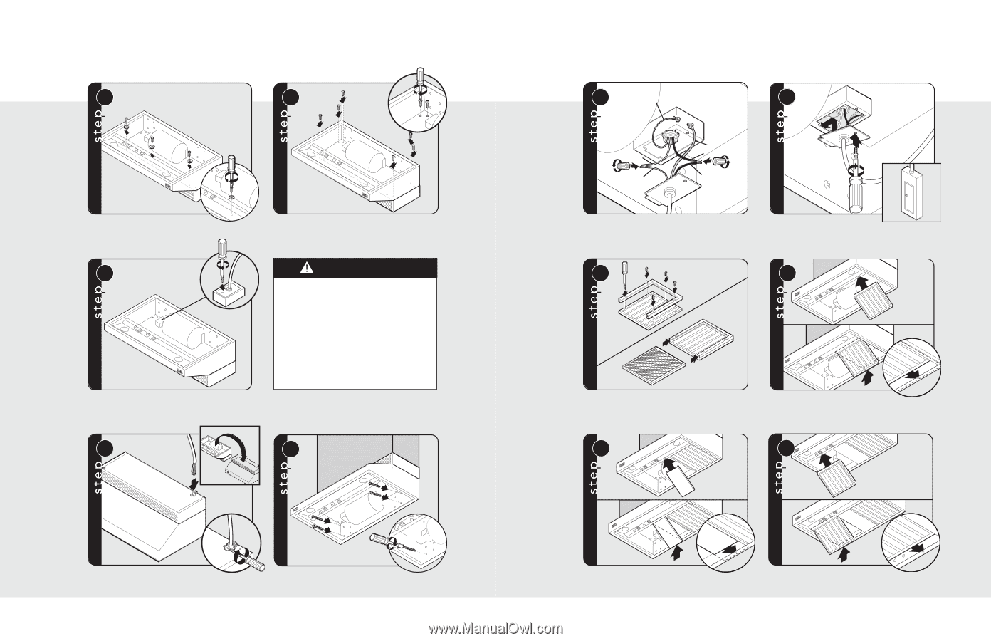
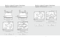
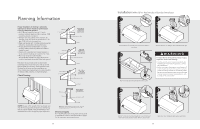
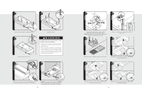
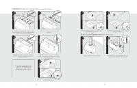
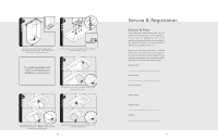
3 4 Attach with screws and lock washers provided. 5 Remove electrical box cover. Attach with screws. WARNING To reduce the risk of fire, electric shock, or injury to persons, observe the following: • Use this unit only in the manner intended by the manufacturer. If you have any questions, contact the manufacturer. • Before servicing or cleaning unit, switch power off at service panel and lock service panel to prevent power from being switched on accidentally. When the service disconnecting means cannot be locked, securely fasten a prominent warning device, such as a tag, to the service panel. 6 7 1 5/16" nut driver 2 Flip hood over. Insert 6" of electrical wiring through the top of vent hood and secure. Refer to local codes. CAUTION: Secure vent hood. Make sure mounting screws are secured into framing. Use additional mounting screws and wall anchors, if necessary. 40 8 BARE OR GREEN WHITE WHITE GREEN BLACK BLACK 9 1 1 2 Connect black to black, white to white, and the green/bare wire under the green screw. NOTE: Housing wiring must be properly installed for wiring to be correct when wiring unit. 10 Replace electrical box cover. Make connection to breaker box. 11 1 Assemble brackets to baffles and insert charcoal filters. 2 3 Slide filter front over front lip. Push filter rear up, then slide back over rear lip. 12 1 13 1 2 3 Slide spacer front over front lip. Push spacer rear up, then slide back over rear lip. 3 2 Slide filter front over front lip. Push filter rear up, then slide back over rear lip. 41
-
 1
1 -
2
-
3
-
4
-
5
-
6
-
7
-
8
-
9
-
10
-
11
-
12
-
13
-
14
-
15
-
 16
16 -
 17
17 -
 18
18 -
 19
19 -
 20
20 -
 21
21 -
 22
22 -
 23
23 -
 24
24
 |
 |