Vizio P50HDTV10A User Manual - Page 11
Left Portion - video inputs
 |
View all Vizio P50HDTV10A manuals
Add to My Manuals
Save this manual to your list of manuals |
Page 11 highlights
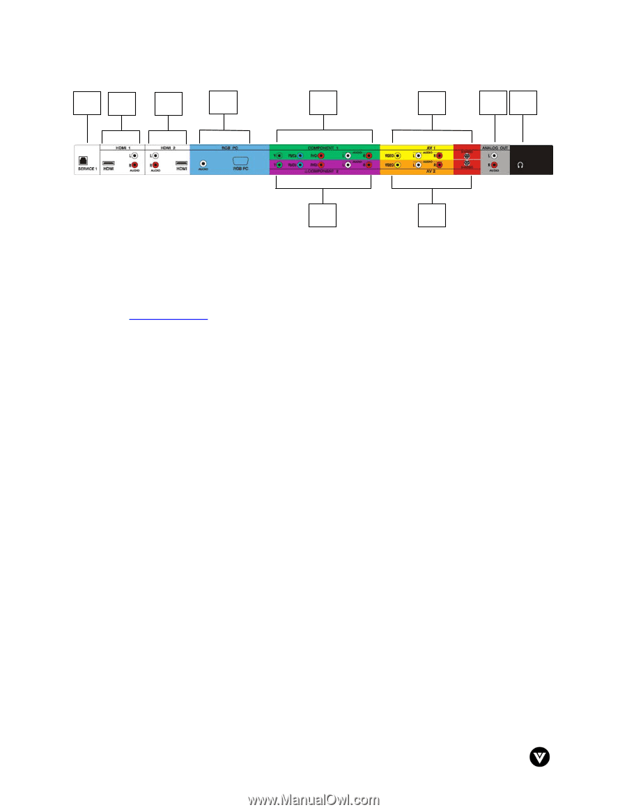
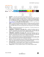
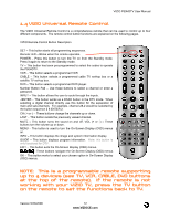
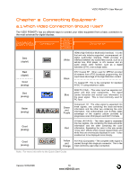
VIZIO P50HDTV User Manual Left Portion 5 6 7 8 9 11 13 14 10 12 5. SERVICE 1 - This custom communication port is for factory service only. 6. HDMI 1 - Connect the primary source for digital video devices such as a DVD multimedia player or set top box through this all digital connector. The white color band on the rear of the TV indicates this connection. For users who want to connect to a DVI enabled device, use a DVI-HDMI cable and connect the Analog Audio output of the device to the L+R AUDIO here. Your VIZIO Certified HDMI and HDMI-DVI cables are available for purchase from www.vizioce.com or by calling 888-VIZIOCE (888-849-4623). 7. HDMI 2 - Connect the secondary source for digital video devices such as a DVD multimedia player or set top box through this all digital connector. The white color band on the rear of the TV indicates this connection. For users who want to connect to a DVI enabled device, use a DVI-HDMI cable and connect the Analog Audio output of the device to the L+R AUDIO here. 8. RGB PC - Connect the video and audio from a computer here. The blue color band on the rear of the TV indicates this connection. 9. COMPONENT 1 (YPb/CbPr/Cr with Audio L/R) - Connect the primary source for component video devices such as a DVD Player or set top box here. From left to right, use green for Y, blue for Pb (or Cb), red for Pr (or Cr), white for left audio and red for right audio inputs. The green color band on the rear of the TV indicates this connection. 10. COMPONENT 2 (YPb/CbPr/Cr with Audio L/R) - Connect the secondary source for component video devices such as a DVD Player or set top box here. From left to right, use green for Y, blue for Pb (or Cb), red for Pr (or Cr), white for left audio and red for right audio inputs. The purple color band on the rear of the TV indicates this connection. 11. AV1 In - Connect the primary source for composite video devices, such as a VCR or video game. Use the white and red connectors to connect the external audio from the same source. The yellow color band on the rear of the TV indicates this connection. 12. AV2 In - Connect the secondary source for composite video devices, such as a VCR or video game. Use the white and red connectors to connect the external audio from the same source. The orange color band on the rear of the TV indicates this connection. 13. Analog Audio Out - Connect the audio from the Plasma TV to an external device, such as a home theatre system, external amplifier or stereo. Speakers cannot be connected directly to here. The gray color band on the rear of the TV indicates this connection. 14. Headphone Out - Connect a headphone directly or use a wireless headphone system. Version 5/23/2006 11 www.VIZIOCE.com
-
 1
1 -
2
-
3
-
4
-
5
-
 6
6 -
 7
7 -
 8
8 -
 9
9 -
 10
10 -
 11
11 -
 12
12 -
 13
13 -
 14
14 -
 15
15 -
 16
16 -
17
-
18
-
19
-
20
-
21
-
22
-
23
-
24
-
25
-
26
-
27
-
28
-
29
-
30
-
31
-
32
-
33
-
34
-
35
-
36
-
37
-
38
-
39
-
40
-
41
-
42
-
43
-
44
-
45
-
46
-
47
-
48
-
49
-
50
-
51
-
52
-
53
-
54
-
55
-
56
-
57
-
58
-
59
-
60
-
61
-
62
-
63
-
64
-
65
-
66
-
67
-
68
-
69
-
70
-
71
-
72
-
73
-
74
-
75
-
76
 |
 |