Weider 240 Tc Bench Uk Manual - Page 6
Assembly
 |
View all Weider 240 Tc Bench manuals
Add to My Manuals
Save this manual to your list of manuals |
Page 6 highlights
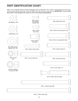
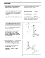
ASSEMBLY To make assembly easier, carefully read the following information and instructions: • Assembly requires two persons. • Because of its weight and size, the weight bench should be assembled in the location where it will be used. Make sure that there is enough clearance to walk around the weight bench as you assemble it. • Place all parts in a cleared area and remove the packing materials. Do not dispose of the packing materials until assembly is completed. • For help identifying small parts, use the PART IDENTIFICATION CHART on page 5. • The following tools (not included) may be required for assembly: two adjustable wrenches one rubber mallet one standard screwdriver one Phillips screwdriver Assembly may be more convenient if you have a socket set, a set of open-end or closed-end wrenches, or a set of ratchet wrenches. 1. Before beginning assembly, make sure that you understand the information in the box above. Orient the Left Base (4) so that the recessed holes are facing the floor. Identify the Left Upright (6), which is marked with a "Left" sticker. Attach the Left Upright to the Left Base (4) with two M10 x 57mm Carriage Bolts (68) and two M10 Black Locknuts (66). Do not tighten the Black Locknuts yet. Make sure that the nut is in the position shown. Attach the Right Upright (7) to the Right Base (5) in the same way. 1 Nut 7 Nut 66 5 4 2. Attach the Crossbar (12) to the Left Upright (6) with two M10 x 65mm Bolts (55), two M10 2 Black Washers (64), and two M10 Black Locknuts (66). Do not tighten the Black 7 Locknuts yet. Attach the Crossbar (12) to the Right Upright (7) in the same way. See steps 1-2. Tighten the M10 Black Locknuts (66). 12 66 66 6 66 Recessed Holes 68 6 64 55 6
-
 1
1 -
 2
2 -
 3
3 -
 4
4 -
 5
5 -
 6
6 -
 7
7 -
 8
8 -
 9
9 -
 10
10 -
 11
11 -
 12
12 -
13
-
14
-
15
-
16
-
17
-
18
-
19
-
20
 |
 |
