Weider 8920 English Manual
Weider 8920 Manual
 |
View all Weider 8920 manuals
Add to My Manuals
Save this manual to your list of manuals |
Weider 8920 manual content summary:
- Weider 8920 | English Manual - Page 1
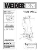
space above for reference.) Serial Number Decal (under seat) ® USER'S MANUAL SEARS, ROEBUCK AND CO. HOFFMAN ESTATES, IL 60179 CAUTION Read all precautions and instructions in this manual before using this equipment. Save this manual for future reference. Visit our website at www.weiderfitness.com - Weider 8920 | English Manual - Page 2
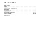
OF CONTENTS IMPORTANT PRECAUTIONS 3 BEFORE YOU BEGIN 4 ASSEMBLY 5 ADJUSTMENT 15 WEIGHT RESISTANCE CHART 17 TROUBLE-SHOOTING AND MAINTENANCE 18 CABLE DIAGRAM 19 EXERCISE GUIDELINES 20 PART LIST 22 EXPLODED DRAWING 23 ORDERING REPLACEMENT PARTS Back Cover FULL 90 DAY WARRANTY Back Cover - Weider 8920 | English Manual - Page 3
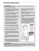
floor or carpet beneath the weight system to protect the floor. 5. Make sure all parts are properly tightened each time the weight system is used. Replace any worn parts immediately. 12. Always stand on the foot plate when performing an exercise that could cause the weight system to tip. 13. Always - Weider 8920 | English Manual - Page 4
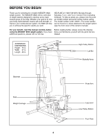
your benefit, read this manual carefully before Before reading further, please review the drawing using the WEIDER® 8920 weight system. If you have below and familiarize yourself with the parts that are additional questions, please call our toll-free labeled. ASSEMBLED DIMENSIONS: Height: 76 in - Weider 8920 | English Manual - Page 5
assembly is completed. • Tighten all parts as you assemble them, unless instructed to do otherwise. • As you assemble the weight system, make sure all parts are oriented as shown in the drawings. • For help identifying small parts, use the PART IDENTIFICATION CHART in the center of this manual - Weider 8920 | English Manual - Page 6
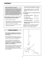
weight tube on the 2 Weight Carriage (19). Note: Make sure the Square Slider Bushings (70) are assembled to the Weight Carriage and Weight Stop (67). Turn the Weight the Front Upright (42) with two M8 x 67mm Bolts (61), a Support Plate (8), and two M8 Nylon Locknuts (3). Attach the Top Frame to - Weider 8920 | English Manual - Page 7
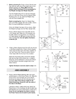
Press Arm. Attach the Press Arm to one side of the Press Frame (17) with two M8 x 63mm Bolts (22) and two M8 Nylon Locknuts (3). Assemble the other Press Arm (46) in the same manner. Handle 22 44 49 46 6. Identify the the Left Arm (47) and Right Arm (48). Note - Weider 8920 | English Manual - Page 8
steps 9 through 22, refer to the CABLE DIAGRAM on page 19 of this manual to verify proper cable routing. Before beginning this section, identify the Short Cable (23) and the Long Cable (58) by comparing the ends of the cables. IMPORTANT: While assembling the cables, do not overtighten the bolts and - Weider 8920 | English Manual - Page 9
) to the bracket on the Top Frame (55) with an M8 x 115mm Bolt (64) and an M8 Nylon Locknut (3). Note: The Pulley Bracket is pre- assembled with a 90mm Pulley (15) and a Cable Trap (66). Route the Long Cable (58) around the 90mm Pulley (15) attached to the Pulley Bracket (20). Be sure that the - Weider 8920 | English Manual - Page 10
Cable (58) to the Weight Carriage (19) with an M10 x 20mm Bolt (69) and 16 an M10 Nylon Locknut (21). 58 21 69 19 17. Attach a 90mm Pulley (15) and a Cable the Short Cable (23). Route the Short 18 Cable under the indicated 90mm Pulley (15) as shown. Be sure that the Cable is between the - Weider 8920 | English Manual - Page 11
Nylon Locknut (21) with an M10 Washer (9) onto each Bolt. Be sure that all parts are oriented as shown. Do not tighten the Nylon Locknuts yet. 42 9 21 16 66 15 16 15 66 20. Route the Short Cable (23) around the 90mm 20 Pulley (15) attached to the lower hole in the - Weider 8920 | English Manual - Page 12
). Do not completely tighten the Nylon Locknut; it should be threaded onto the end of the Cable until two threads are showing above the Nylon Locknut, as shown in the inset drawing. 3 68 57 23 3 SEAT ASSEMBLY 68 57 23 23 23. Attach the Backrest (41) to the Front Upright (42) with - Weider 8920 | English Manual - Page 13
24. Press a 38mm Square Inner Cap (32) into the Seat Frame (36). 24 Insert the M6 x 50mm Carriage Bolt (38) into the center hole in the Seat Plate (37). Attach the Seat Plate to the Seat (13) with two M6 x 16mm Screws (18). Insert the M6 x 50mm Carriage Bolt (38) into the indicated hole in the - Weider 8920 | English Manual - Page 14
the problem. IMPORTANT: If the cables are not properly routed, they may be damaged when heavy weight is used. See the CABLE DIAGRAM on page 19 of this manual for proper cable routing. If there is any slack in the cables, you will need to remove it by tightening the cables; see TROUBLE-SHOOTING - Weider 8920 | English Manual - Page 15
ADJUSTMENT The instructions below describe how each part of the weight system can be adjusted. Refer to the exercise guide accompanying this manual to see how the weight system should be set up for each exercise. IMPORTANT: When attaching the lat bar or nylon strap, make sure that the attachments - Weider 8920 | English Manual - Page 16
the M8 x 67mm Carriage Bolt (14) and the Seat Knob (40). For some exercises, the Seat (13) must be removed. First, be sure that the chain is not M10 x 63mm Eyebolt (35) with a Cable Clip (53). Attach the other end of the Chain to the Short Cable (23) with a Cable Clip. Note: Be sure the Eyebolt is - Weider 8920 | English Manual - Page 17
WEIGHT RESISTANCE CHART This chart shows the approximate weight resistance at each weight station. The column labeled "WEIGHT" refers to the amount of weight, in pounds, placed on the weight carriage. The weight resistance shown for the butterfly arm station is for each butterfly arm. Note: The - Weider 8920 | English Manual - Page 18
TROUBLE-SHOOTING AND MAINTENANCE Make sure all parts are properly tightened each time you use the weight system. Replace any worn parts immediately. The weight system can be cleaned using a damp cloth and mild non-abrasive detergent. Do not use solvents. TIGHTENING THE CABLES Woven cable, the - Weider 8920 | English Manual - Page 19
CABLE DIAGRAM The cable diagram below shows the proper routing of the Short Cable (23) and the Long Cable (58). Use the diagram to be sure that the two cables and the cable traps have been assembled correctly. If the cables have not been correctly routed, the weight system will not function properly - Weider 8920 | English Manual - Page 20
the appropriate parts of the body. Exercising in an uncontrolled manner will leave you feeling exhausted. On the exercise guide accompanying this manual you will find photographs showing the correct form for several exercises, and a list of the muscles affected. Refer to the muscle chart on page - Weider 8920 | English Manual - Page 21
of sets and repetitions completed. Record your weight and key body measurements at the end of every month. Remember, the key to achieving the greatest results is to make exercise a regular and enjoyable part of your everyday life. MUSCLE CHART A. Sternomastoid (neck) B. Pectoralis Major (chest - Weider 8920 | English Manual - Page 22
PART IDENTIFICATION CHART-Model No. 831.159711 R0102A M10 Washer (9) 25mm Round Cover Cap (62) M8 Washer (68) M6 Washer (10) 25mm Round Inner Cap (49) M10 Nylon - Weider 8920 | English Manual - Page 23
50mm Square Outer Cap (51) 50mm Square Inner Cap (27) 45mm Square Inner Cap (44) M6 x 63mm Screw (43) M10 x 60mm Bolt (7) M8 x 63mm Bolt (22) M8 x 67mm Bolt (61) M8 x 63mm Carriage Bolt (1) M8 x 70mm Bolt (11) M8 x 67mm CarriageBolt (14) M10 x 80mm Bolt (25) M10 x 90mm Bolt (16) M8 x 115mm Bolt (64 - Weider 8920 | English Manual - Page 24
"V"-Pulley (6) (Not shown to scale) 90mm Pulley (15) (Not shown to scale) - Weider 8920 | English Manual - Page 25
x 115mm Bolt 65 1 25mm Square Inner Cap 66 5 Cable Trap 67 1 Weight Stop 68 1 M8 Washer 69 1 M10 x 20mm Bolt 70 3 Square Slider Bushing # 1 User's Manual # 1 Exercise Guide Note: "#" indicates a non-illustrated part. Specifications are subject to change without notice. 22 - Weider 8920 | English Manual - Page 26
EXPLODED DRAWING-Model No. 831.159711 64 20 21 66 3 12 15 27 8 61 56 66 15 55 61 8 15 12 49 44 16 15 3 58 21 44 21 60 63 62 7 50 6 21 50 7 48 6 3 21 42 44 45 13 R0102A 60 63 62 47 44 45 21 3 68 57 49 12 70 23 21 3 67 5 51 58 49 69 10 43 19 70 11 51 3 9 21 3 31 14 - Weider 8920 | English Manual - Page 27
find that: • you need help assembling or operating the WEIDER® 8920 weight system • a part is missing • or you need to schedule repair service call our toll-free HELPLINE 1-800-736-6879 Monday-Saturday, 7 am-7 pm Central Time (excluding holidays) REPLACEMENT PARTS If parts become worn and need to be
-
 1
1 -
 2
2 -
 3
3 -
 4
4 -
 5
5 -
 6
6 -
 7
7 -
8
-
9
-
10
-
11
-
12
-
13
-
14
-
15
-
16
-
17
-
18
-
19
-
20
-
21
-
22
-
23
-
24
-
25
-
26
-
27
 |
 |
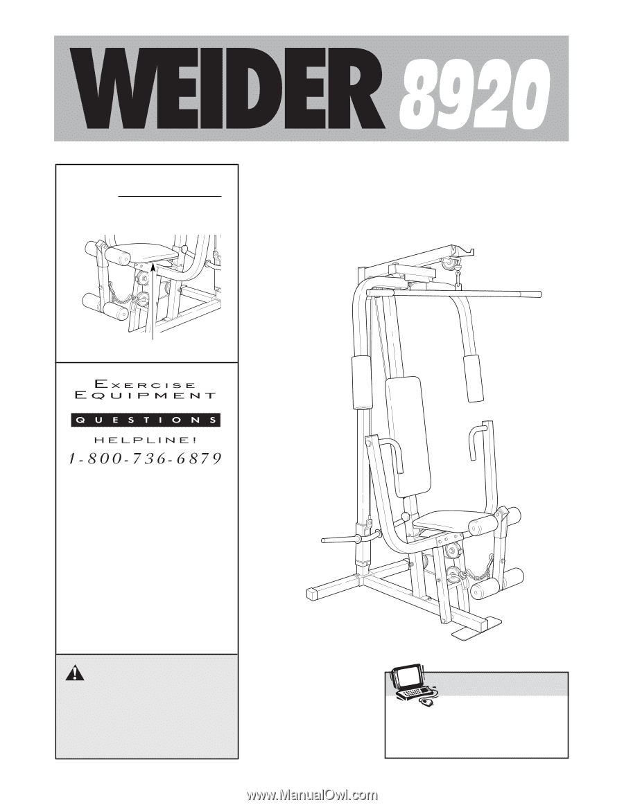
USER'S MANUAL
®
CAUTION
Read all precautions and instruc-
tions in this manual before using
this equipment. Save this manual
for future reference.
Model No. 831.159711
Serial No.
(Write the serial number in the
space above for reference.)
Serial Number Decal (under seat)
Visit our website at
www.weiderfitness.com
new products, prizes,
fitness tips, and much more!
SEARS, ROEBUCK AND CO.
HOFFMAN ESTATES, IL 60179