Weider 8920 English Manual - Page 7
Press a Butterfly Arm Bushing 60 into each Arm.
 |
View all Weider 8920 manuals
Add to My Manuals
Save this manual to your list of manuals |
Page 7 highlights
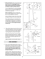
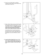
5. Press a 45mm Square Inner Cap (44) into the top 5 of one of the Press Arms (46). Press a 25mm Round Inner Cap (49) into each end of the handle on the Press Arm. Attach the Press Arm to one side of the Press Frame (17) with two M8 x 63mm Bolts (22) and two M8 Nylon Locknuts (3). Assemble the other Press Arm (46) in the same manner. Handle 22 44 49 46 6. Identify the the Left Arm (47) and Right Arm (48). Note the position of the welded bracket on each 6 Arm. Arm identification is important for step 7. Press a Butterfly Arm Bushing (60) into each Arm. 60 Welded Brackets 3 17 47 48 7. Lubricate both axles on the Top Frame (55). Slide the Right Arm (48) onto the right axle of the Top Frame (55). Note: Be careful not to confuse the Right Arm with the Left Arm (47); refer to step 6 to identify the Right Arm. Be sure that the upper end of the Right Arm is behind the indicated bracket on the Top Frame. Tap two 25mm Retainers (63) and a 25mm Round Cover Cap (62) onto the right axle of the Top Frame (55). Be sure that the teeth on the Retainers bend toward the Cover Cap, as shown in the inset drawing. Attach the Left Arm (47) in the same manner. Press two 45mm Square Inner Caps (44) into the lower ends of the Left and Right Arms (47, 48). Wet the lower end of each Arm with soapy water. Slide a Large Foam Pad (45) onto the lower end of each Arm. 7 48 44 45 7 55 47 Bracket Lubricate Axle 63 62 45 55 63 62
-
 1
1 -
 2
2 -
 3
3 -
 4
4 -
 5
5 -
 6
6 -
 7
7 -
 8
8 -
 9
9 -
 10
10 -
 11
11 -
 12
12 -
13
-
14
-
15
-
16
-
17
-
18
-
19
-
20
-
21
-
22
-
23
-
24
-
25
-
26
-
27
 |
 |
