Weider 8920 English Manual - Page 9
Note: The Pulley Bracket is pre - cable routing
 |
View all Weider 8920 manuals
Add to My Manuals
Save this manual to your list of manuals |
Page 9 highlights
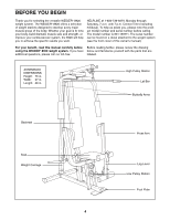
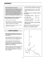
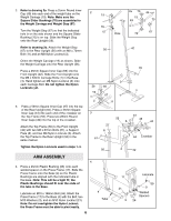
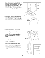
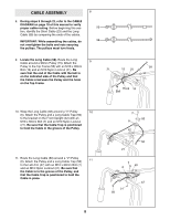
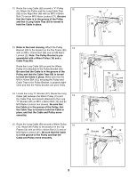
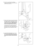
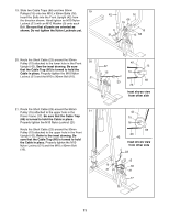
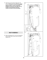
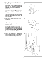
12. Route the Long Cable (58) around a "V"-Pulley 12 (6). Attach the Pulley and the Long Cable Trap (50) to the Right Arm (48) with an M10 x 60mm Bolt (7) and an M10 Nylon Locknut (21). Be sure that the Cable is in the groove of the Pulley and that a Long Cable Trap (50) is turned to hold the Cable in place. 50 7 6 58 48 21 13. Refer to the inset drawing. Attach the Pulley 13 Bracket (20) to the bracket on the Top Frame (55) with an M8 x 115mm Bolt (64) and an M8 Nylon Locknut (3). Note: The Pulley Bracket is pre- assembled with a 90mm Pulley (15) and a Cable Trap (66). Route the Long Cable (58) around the 90mm Pulley (15) attached to the Pulley Bracket (20). Be sure that the Cable is in the groove of the Pulley and that the Cable Trap (66) is turned to hold the Cable in place. Make sure that the M10 x 45mm Bolt (12), securing the Pulley and Cable Trap to the Pulley Bracket, is properly tightened and that the Pulley Bracket can pivot freely. 14. Locate the Long "U"-Bracket (57). Route the Long Cable (58) between the 90mm Pulley (15) and 14 the Cable Trap (not shown) attached to the Long "U"-Bracket with an M10 x 45mm Bolt (12) and an M10 Nylon Locknut (not shown). Be sure that the Cable is in the groove of the Pulley, that the Cable Trap is turned to hold the Cable in place, and that the Cable and Pulley move smoothly. 15. Route the Long Cable (58) around a 90mm Pulley 15 (15). Attach the Pulley to the bracket on the Top Frame (55) with an M10 x 45mm Bolt (12) and an M10 Nylon Locknut (21). Be sure that the Cable is in the groove of the Pulley and that the Cable and Pulley move smoothly. 66 20 15 12 58 55 64 20 3 15 58 57 12 55 58 Bracket 15 12 21 9
-
 1
1 -
2
-
3
-
 4
4 -
 5
5 -
 6
6 -
 7
7 -
 8
8 -
 9
9 -
 10
10 -
 11
11 -
 12
12 -
 13
13 -
 14
14 -
15
-
16
-
17
-
18
-
19
-
20
-
21
-
22
-
23
-
24
-
25
-
26
-
27
 |
 |
