Weider Club C670 Bench English Manual - Page 8
grease. Attach the Leg Lever 5 to the Leg Lever
 |
View all Weider Club C670 Bench manuals
Add to My Manuals
Save this manual to your list of manuals |
Page 8 highlights
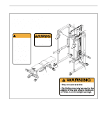
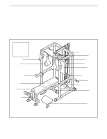
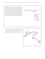
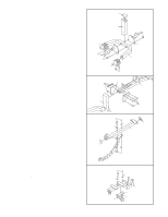
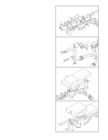
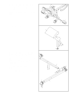
6. Pull out the Small Adjustment Knob (23) that is nearer the Stabilizer (2). Insert the Backrest Bracket (16) between the tubes on the Bench Frame (1) and engage the Small Adjustment Knob into one of the holes in the Bracket. Pull out the Small Adjustment Knob (23) by the Seat Bracket Sleeve (93). Insert the Seat Bracket (17) into the Seat Bracket Sleeve and engage the Small Adjustment Knob into one of the holes in the Bracket. Lubricate the M10 x 102mm Bolt (99) with grease. Attach the Seat Frame (7) and the Backrest Frame (6) to the Bench Frame (1) with the Bolt, two M10 Washers (35), and an M10 Nylon Locknut (34). Do not overtighten the Locknut; the Seat and Backrest Frames must be able to pivot easily. Attach an M10 x 19mm Bolt (102) to the round hole in the Seat Bracket (17) with an M10 Nylon Locknut (34). Tighten the M10 Nylon Locknuts (34) used in step 5. 7. Press three 50mm Square Inner Caps (13) and a 48mm Round Inner Cap (19) into the Leg Lever (5). Lubricate the M10 x 85mm Bolt (103) with grease. Attach the Leg Lever (5) to the Leg Lever Bracket (18) with the Bolt and an M10 Nylon Locknut (34). Loosen the Adjustment Knob (22) by turning it counterclockwise several turns. Pull the Knob out and slide the Leg Lever Bracket (18) into the Seat Frame (7). Tighten the Adjustment Knob into the Leg Lever Bracket. 8. Attach the Backrest (11) to the Backrest Frame (6) with four M6 x 16mm Screws (29) 9. Attach the Seat (10) to the Seat Frame (7) with four M6 x 16mm Screws (29) 6 35 34 99 23 7 17 6 23 34 102 7 5 13 35 2 1 16 93 Lubricate 34 13 Lubricate 18 7 22 103 19 13 8 11 6 29 29 9 10 29 8
-
 1
1 -
2
-
 3
3 -
 4
4 -
 5
5 -
 6
6 -
 7
7 -
 8
8 -
 9
9 -
 10
10 -
 11
11 -
 12
12 -
 13
13 -
14
-
15
-
16
-
17
-
18
-
19
-
20
-
21
-
22
-
23
-
24
-
25
-
26
-
27
-
28
-
29
-
30
-
31
-
32
-
33
-
34
 |
 |
