Weider Cross Bow By 1500x Canadian English Manual - Page 16
Cable Diagram
 |
View all Weider Cross Bow By 1500x manuals
Add to My Manuals
Save this manual to your list of manuals |
Page 16 highlights
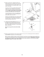
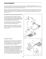
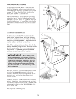
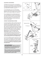
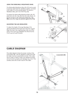
USING THE REMOVABLE RESISTANCE BARS The Removable Resistance Bars (36, 67) can be used to exercise apart from the resistance system, as shown in the video or on the exercise guide. To remove a Resistance Bar, pull it out of the Tray (35). To replace the Removable Resistance Bars (36, 67), slide them into the Tray (35) from the side shown, so that the arrows on the rings point toward the Tray. Make sure the rings are pushed against the Tray. ADJUSTING THE LEG DEVELOPER To adjust the height of the Leg Developer (19), remove the Bench Knob (42) from the Front Leg (6). Align the hole in the Leg Developer with one of the holes in the Front Leg. Retighten the Knob into the Front Leg and Leg Developer. 67 36 35 Rings 19 5 42 6 CABLE DIAGRAM The cable diagram shows the proper routing of the Long Cable (80). Use the diagram to make sure that the cable has been assembled correctly. If the cable has not been correctly routed, the resistance system will not function properly and damage may occur. The numbers show the correct route for the cable. 5 Long Cable (80) 76 4 3 2 1 16
-
 1
1 -
2
-
3
-
4
-
5
-
6
-
7
-
8
-
9
-
10
-
 11
11 -
 12
12 -
 13
13 -
 14
14 -
 15
15 -
 16
16 -
 17
17 -
 18
18 -
 19
19 -
 20
20 -
 21
21 -
22
-
23
 |
 |
