Weider Cross Bow By 1500x Canadian English Manual - Page 8
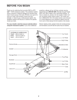
Note: The Top Resistance Bar is closer
 |
View all Weider Cross Bow By 1500x manuals
Add to My Manuals
Save this manual to your list of manuals |
Page 8 highlights
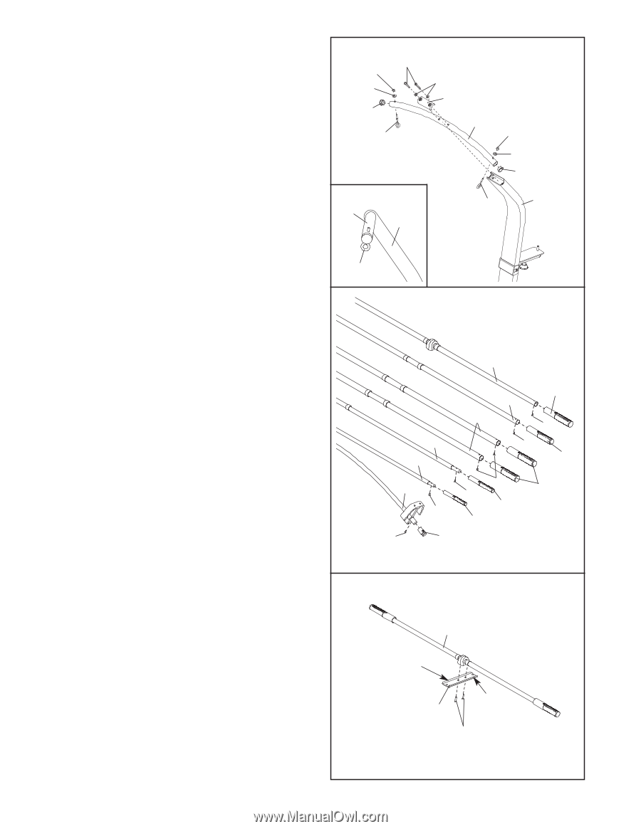
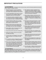
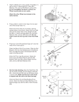
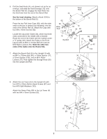
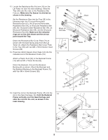
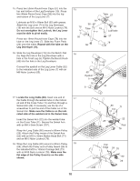
9. Press two 38mm Round Inner Caps (38) into the ends of the Top Frame (10). Attach two Eyebolts (34) to the Top Frame (10) with two M8 Washers (59) and two M8 Nylon Locknuts (65). Do not overtighten the Locknuts; the Eyebolts must be able to rotate freely. Attach the Top Frame (10) to the Lat Tower (4) with two M10 x 65mm Button Head Screws (70), two M10 Washers (75), and the Top Frame Cover (93). Make sure that the Eyebolts (34) are oriented as shown in the inset drawing. If they are not, turn the Top Frame around and reattach it. 9 70 65 59 38 34 Side View 10 4 75 93 10 65 59 38 34 4 10. Attach the two 10-pound Short Resistance Bar Caps (20) to the 10-pound Resistance Bar (44) with two M4 x 12mm Flat Head Screws (85). Using twelve M4 x 12mm Flat Head Screws (85), attach the two 10-pound Resistance Bar Caps (101) to the 10-pound Removable Resistance Bar (67), the two 20-pound Resistance Bar Caps (88) to the 20-pound Removable Resistance Bar (36), the six 80-pound Resistance Bar Caps (100) to the two 80-pound Resistance Bars (95) and the 80-pound Top Resistance Bar (111), and the two 40-pound Resistance Bar Caps (79) to the 40pound Resistance Bar (96). 34 10 111 36 67 100 96 95 85 85 79 44 85 100 85 85 88 101 85 20 11. Orient the Resistance Bar Cover Plate (72), with 11 the edges up. Attach the 80-pound Top Resistance Bar (111) to the Resistance Bar Cover Plate with the two 1/4" x 25mm Flat Head Screws (112). Note: The Top Resistance Bar is closer to the back of the Cover Plate. 111 Edges up Back 72 112 8
-
 1
1 -
2
-
 3
3 -
 4
4 -
 5
5 -
 6
6 -
 7
7 -
 8
8 -
 9
9 -
 10
10 -
 11
11 -
 12
12 -
 13
13 -
14
-
15
-
16
-
17
-
18
-
19
-
20
-
21
-
22
-
23
 |
 |