Weider Cross Bow By 1500x Canadian English Manual - Page 9
Hold the Backrest
 |
View all Weider Cross Bow By 1500x manuals
Add to My Manuals
Save this manual to your list of manuals |
Page 9 highlights
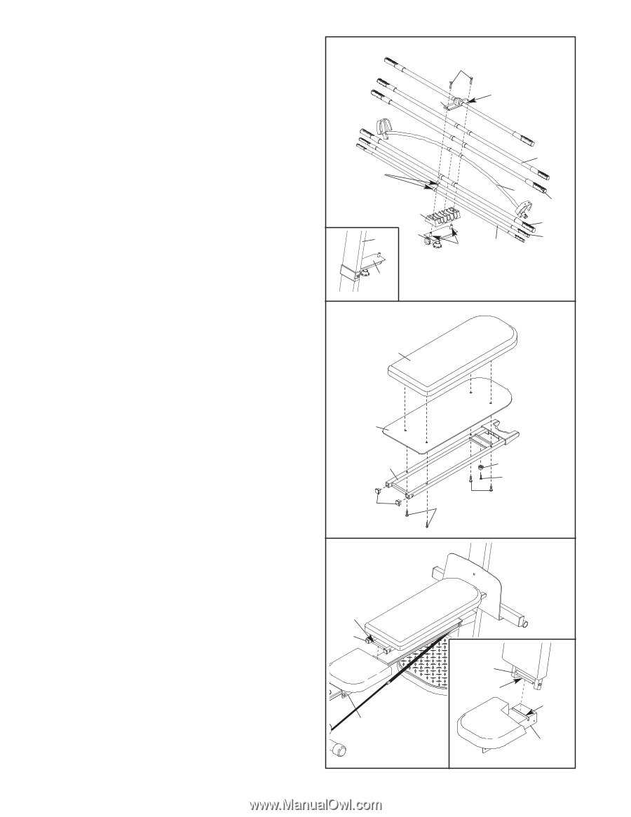
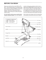
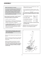
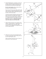
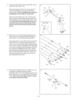
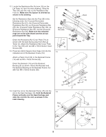
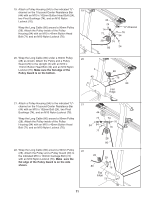
12. Locate the Resistance Bar Fulcrum (18) on the Lat Tower (4) (see the inset drawing). Slide the Tray (35) onto the rods on the Resistance Bar Fulcrum. Make sure the Spacer is oriented as shown in the drawing. Set the Resistance Bars into the Tray (35) in the following order: the 10-pound Removable Resistance Bar (67), the 20-pound Removable Resistance Bar (36), an 80-pound Resistance Bar (95), the 10-pound Center Resistance Bar (44), an 80-pound Resistance Bar (95), and the 40-pound Resistance Bar (96). Make sure the indicated rings are on the side shown and the arrows point toward the Tray. Orient the Resistance Bar Cover Plate (72) as shown with the back facing away from the Lat Tower (4). Attach the Resistance Bar Cover Plate to the Tray (35) with two M8 x 19mm Button Head Screws (86). 13. Press two 25mm Square Inner Caps (54) into the indicated end of the Backrest Frame (15). Attach a Plastic Foot (53) to the Backrest Frame (15) with an M4 x 16mm Screw (62). Orient the Backrest (14) and the Backrest Backing (8) as shown. Attach the Backrest and the Backrest Backing to the Backrest Frame (15) with four M6 x 45mm Screws (58). 12 86 72 Back Rings on this side 35 4 18 18 13 14 96 44 95 95 36 Rods 67 8 15 54 14. Insert the rod on the Backrest Frame (15) into the slot in the Seat Carriage (12). Hold the Backrest Frame vertically over the Seat Carriage and slide the rod into the slot, as shown in the inset drawing. 14 Rod 15 12 53 62 58 58 15 Rod Slot 12 9
-
 1
1 -
2
-
3
-
 4
4 -
 5
5 -
 6
6 -
 7
7 -
 8
8 -
 9
9 -
 10
10 -
 11
11 -
 12
12 -
 13
13 -
 14
14 -
15
-
16
-
17
-
18
-
19
-
20
-
21
-
22
-
23
 |
 |