Weider Cross Bow By 1500x Canadian English Manual - Page 6
M6 x 16mm Screws 82 and two M6 Black Nylon
 |
View all Weider Cross Bow By 1500x manuals
Add to My Manuals
Save this manual to your list of manuals |
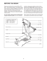
Page 6 highlights
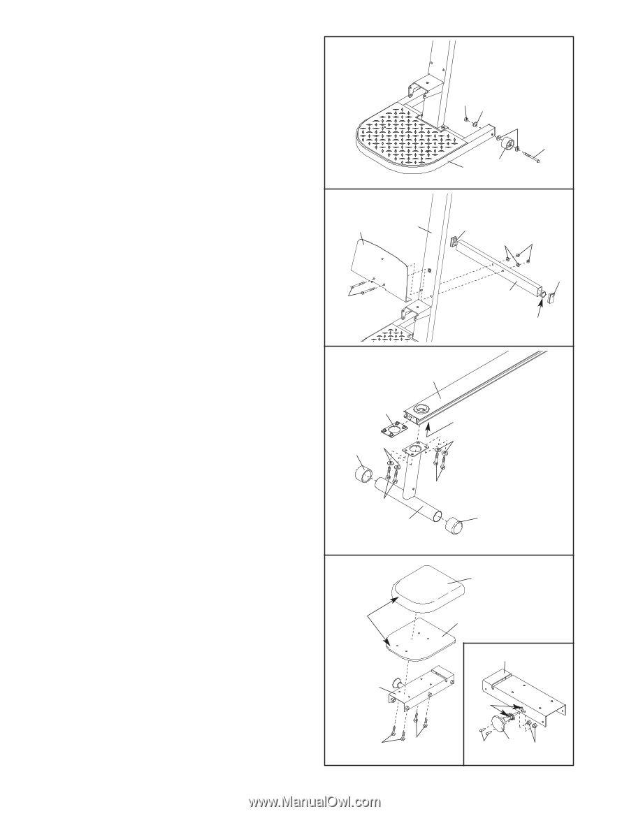
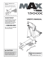
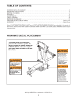
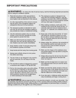
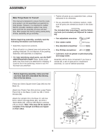
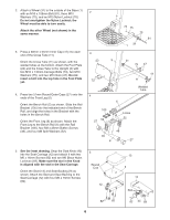
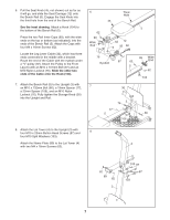
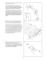
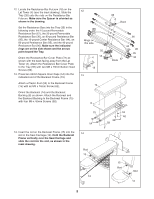
2. Attach a Wheel (31) to the outside of the Base (1) with an M10 x 108mm Bolt (81), three M10 Washers (75), and an M10 Nylon Locknut (76). Do not overtighten the Nylon Locknut; the Wheel must be able to turn easily. Attach the other Wheel (not shown) in the same manner. 3. Press a 38mm x 64mm Inner Cap (41) into each end of the Cross Tube (11). Orient the Cross Tube (11) as shown, with the welded tubes at the bottom. Attach the Foot Plate (23) and the Cross Tube to the Upright (3) with two M10 x 140mm Carriage Bolts (73), two M10 Washers (75), and two M10 Nuts (47). Do not insert a bolt into the top hole in the Foot Plate yet. 4. Press two 57mm Round Outer Caps (27) onto the ends of the Front Leg (6). Orient the Bench Rail (5) as shown. Slide the Rail Bracket (105) into the indicated end of the Bench Rail, and align the holes in the Bracket with the holes in the Bench Rail. Orient the Front Leg (6) as shown. Attach the Front Leg to the Bench Rail (5) with the Rail Bracket (105), four M8 x 25mm Button Screws (46), and four M8 Split Washers (52). 2 3 23 76 75 75 81 1 31 3 41 75 47 73 4 105 27 52 41 11 Welded Tube 5 Holes 52 46 46 6 27 5. See the inset drawing. Snap the Seat Knob (45) into the Seat Carriage (12) and attach it with two M6 x 16mm Screws (82) and two M6 Black Nylon Locknuts (69). Make sure the slot in the Knob is aligned with the slot in the Seat Carriage. Orient the Seat (13) and Seat Backing (9) as shown. Attach the Seat and Seat Backing to the Seat Carriage (12) with four M6 x 16mm Screws (82). 5 Round End 12 13 9 12 Slot 82 82 6 82 45 69
-
 1
1 -
 2
2 -
 3
3 -
 4
4 -
 5
5 -
 6
6 -
 7
7 -
 8
8 -
 9
9 -
 10
10 -
 11
11 -
 12
12 -
13
-
14
-
15
-
16
-
17
-
18
-
19
-
20
-
21
-
22
-
23
 |
 |