Weider Pro 7000 Uk Manual - Page 10
Pulley 24. Attach the Pulley and a Cable Trap
 |
View all Weider Pro 7000 manuals
Add to My Manuals
Save this manual to your list of manuals |
Page 10 highlights
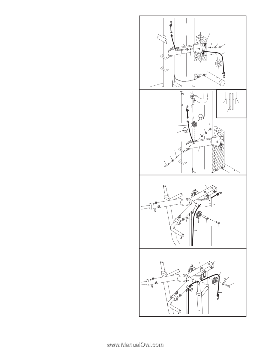
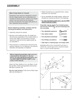
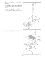
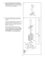
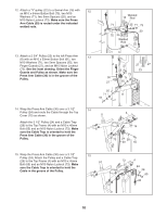
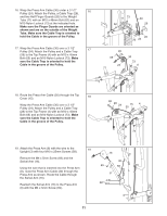
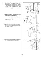
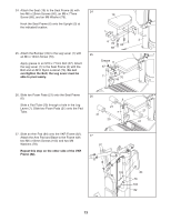
12. Attach a "V"-pulley (22) to a Swivel Arm (16) with 12 an M10 x 64mm Button Bolt (75), two M10 Washers (71), two 5mm Spacers (25), and an M10 Nylon Locknut (73). Make sure the Press Arm Cable (30) is routed under the indicated welded rods. Welded 16 Rod 71 25 71 73 75 25 Welded Rod 30 22 13. Attach a 2 3/4" Pulley (23) to the left Press Arm (8) with an M10 x 53mm Button Bolt (61), two M10 Washers (71), two 5mm Spacers (25), two Finger Guards (27), and an M10 Nylon Locknut (73). See the inset drawing. Orient the Finger Guards and Pulley as shown. Make sure the Press Arm Cable (30) is in the groove of the Pulley. 13 27 27 27 23 23 73 30 71 27 25 25 71 8 61 14. Wrap the Press Arm Cable (30) over a 3 1/2" 14 Pulley (24) and route the Cable through the Top Cover (15) as shown. Attach the 3 1/2" Pulley (24) and a Cable Trap (28) to the Top Frame (4) with an M10 x 45mm Bolt (65) and an M10 Nylon Locknut (73). Make sure the Cable Trap is oriented to hold the Press Arm Cable (30) in the groove of the Pulley. 4 15 73 24 28 30 65 15. Wrap the Press Arm Cable (30) over a 3 1/2" 15 Pulley (24). Attach the Pulley and a Cable Trap (28) to the Top Frame (4) with an M10 x 45mm Bolt (65) and an M10 Nylon Locknut (73). Make sure the Cable Trap is oriented to hold the Cable in the groove of the Pulley. 73 4 24 28 65 30 10
-
 1
1 -
2
-
3
-
4
-
 5
5 -
 6
6 -
 7
7 -
 8
8 -
 9
9 -
 10
10 -
 11
11 -
 12
12 -
 13
13 -
 14
14 -
 15
15 -
16
-
17
-
18
-
19
-
20
-
21
-
22
-
23
-
24
 |
 |