Weider Pro 7000 Uk Manual - Page 17
Cable Diagram, Weight Resistance Chart
 |
View all Weider Pro 7000 manuals
Add to My Manuals
Save this manual to your list of manuals |
Page 17 highlights
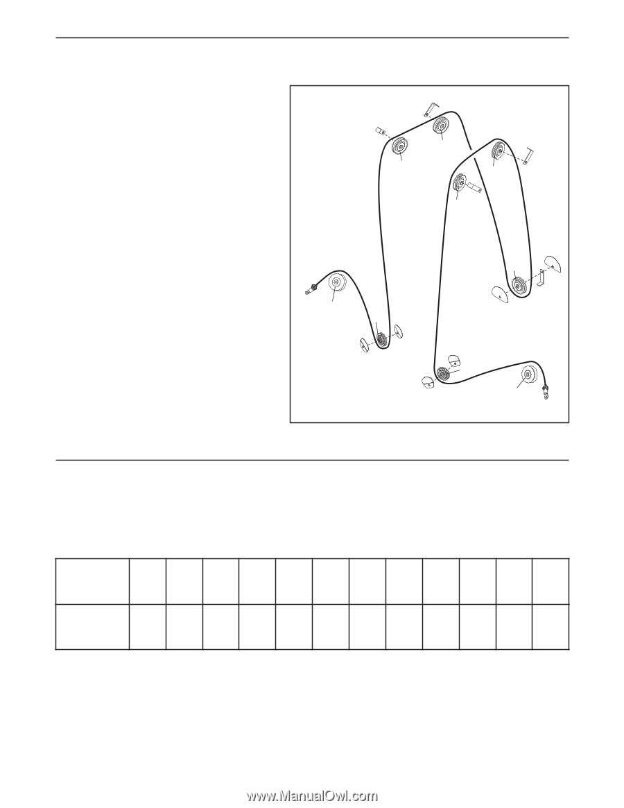
CABLE DIAGRAM The cable diagram shows the proper routing of the Press Arm Cable (30). Use the diagram to make sure that the Cable has been assembled correctly. If the Cable has not been correctly routed, the weight system will not function properly and damage may occur. The numbers show the correct route for the Cable. Press Arm Cable (30) 7 6 4 3 9 8 5 2 1 WEIGHT RESISTANCE CHART The chart below shows the approximate weight resistance for the 12.5 lb. weights. Weight resistance shown is for each arm. Note: The actual resistance at each station may vary due to differences in individual weight plates as well as friction between the cables, pulleys, and weight guides. WEIGHT 1 2 3 4 5 6 7 8 9 10 11 12 RESISTANCE 14 23 32 41 50 59 68 77 86 95 102 110 17
-
 1
1 -
2
-
3
-
4
-
5
-
6
-
7
-
8
-
9
-
10
-
11
-
 12
12 -
 13
13 -
 14
14 -
 15
15 -
 16
16 -
 17
17 -
 18
18 -
 19
19 -
 20
20 -
 21
21 -
 22
22 -
23
-
24
 |
 |