Weider Viper 2000 Uk Manual - Page 11
end of the I Plates 78. Route the Short Cable
 |
View all Weider Viper 2000 manuals
Add to My Manuals
Save this manual to your list of manuals |
Page 11 highlights
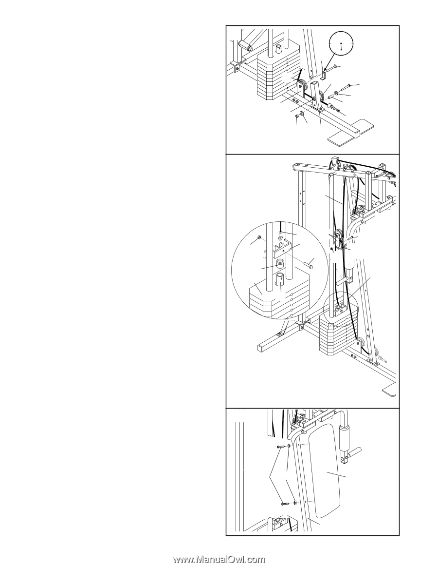
23. Hold the indicated end of the Short Cable (23) under the 3 1/2" Pulley (15) on the Front Upright (42). Attach the 5/16" x 3 1/2" Bolt (87), two 5/16" Flat Washers (8), the 1" Metal Spacer (22), and a 5/16" Nylon Locknut (3) to the Front Upright as shown. Be sure that the Short Cable is between the Pulley and the Metal Spacer. Tighten the 3/8" Nylon Locknut (21) and 3/8" x 3 1/2" Bolt (not shown). Wrap the Short Cable (23) up around the 3 1/2" Pulley (15) on the Pulley Plate (20). Tighten the 3/8" Nylon Locknut (21) and 3/8" x 1 3/4" Bolt (48). Make sure that the Cable Trap (59) is in the 6 o'clock position. 24. Remove the 3/8" Nylon Locknut (21), 3/8" x 1 3/4" Bolt (48), and 4 1/2" Pulley (77) from the lower end of the "I" Plates (78). Route the Short Cable (23) over the Pulley and reattach the Pulley to the "I" Plates with the Bolt and Nylon Locknut. Refer to the inset drawing. Slide the Plastic Flanged Bushing (103) onto the Weight Tube (80). Press the Plastic Flanged Bushing into the top Weight (25). Slide the Weight Guide Bracket (81) onto the top of the Weight Tube. Tap the Weight Guide Bracket with a mallet to ensure that the Plastic Flanged Bushing is firmly in the top Weight. Insert the end of the Short Cable (23) into the upper end of the Weight Tube (80). Insert a 5/16" x 1 1/2" Bolt (24) through the Weight Guide Bracket (81), Weight Tube, and Short Cable. Tighten a 5/16" Nylon Locknut (3) onto the Bolt. IMPORTANT: The Short and Long Cables (23, 66) must be properly routed on the Pulleys, and the Cables must be properly tightened. To tighten the Cables, refer to TIGHTENING THE CABLES on page 18 of this manual. 23 12 9 3 6 59 48 15 15 87 8 20 22 21 23 3 8 42 24 66 3 103 25 23 78 81 24 21 48 77 23 80 25. Attach the Backrest (41) to the Front Upright (42) 25 with two 1/4" x 2 1/2" Screws (43) and 1/4" Flat Washers (10). 43 10 41 42 11
-
 1
1 -
2
-
3
-
4
-
5
-
 6
6 -
 7
7 -
 8
8 -
 9
9 -
 10
10 -
 11
11 -
 12
12 -
 13
13 -
 14
14 -
 15
15 -
 16
16 -
17
-
18
-
19
-
20
-
21
-
22
-
23
-
24
-
25
-
26
-
27
 |
 |