Weider Viper 2000 Uk Manual - Page 7
upper end of the Weight Tube. The Weight Tube
 |
View all Weider Viper 2000 manuals
Add to My Manuals
Save this manual to your list of manuals |
Page 7 highlights
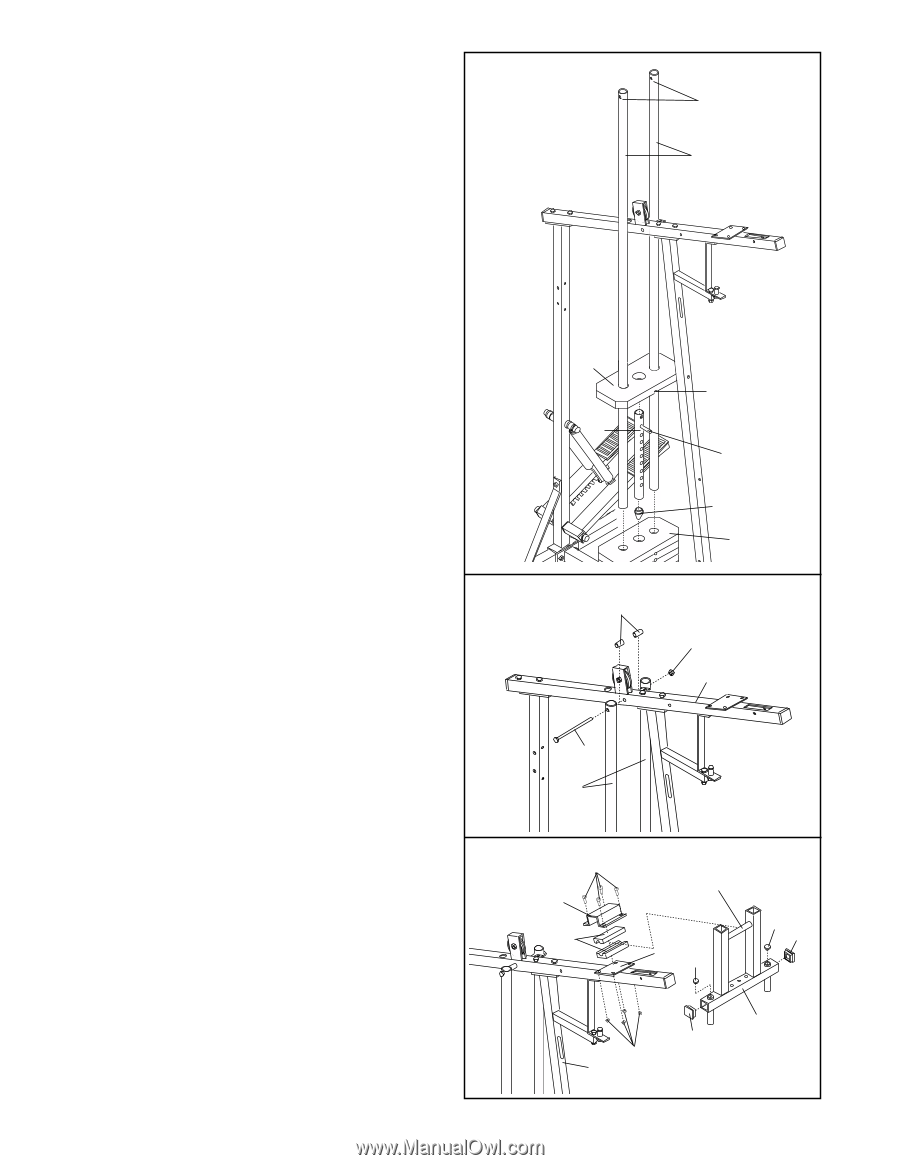
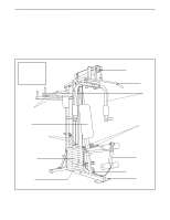
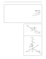
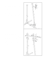
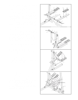
9. Press the Weight Tube Endcap (79) into the indi- 9 cated end of the Weight Tube (80). Insert the Weight Tube (80) into the stack of Weights (25). Slide the tenth Weight (25) onto the upper end of the Weight Tube. The Weight Tube must be turned so the welded pin is in the pin groove in the Weight. Locate the lower ends of the Weight Guides (72) (there are holes near the upper ends). Insert the lower ends of the Weight Guides into the ten Weights (25). Upper Ends of Weight Guides have Holes 72 10. Attach the upper ends of the Weight Guides (72) 10 to the Top Frame (67) with the 5/16" x 6" Bolt (74), the two 1/2" x 3/4" Bushings (73), and a 5/16" Nylon Locknut (3). 25 80 73 Pin Groove Welded Pin 79 25 3 67 11. Press two 1 3/4" Inner Caps (44) and two 1" Round Inner Caps (49) into the Arm Frame (52). 11 Lubricate the upper axle on the Arm Frame (52). Hold the axle between the two Arm Frame Bushings (68). Set the Arm Frame Bushings and the Arm Frame on the welded plate on the Top Frame (67). Place the Arm Frame Bracket (69) over the Arm Frame Bushings. Attach the Arm Frame Bracket to the Top Frame with four 1/4" x 3/4" Screws (18) and 1/4" Nylon Locknuts (7). 7 74 72 18 69 68 Lubricate 67 49 49 44 52 44 7 42
-
 1
1 -
 2
2 -
 3
3 -
 4
4 -
 5
5 -
 6
6 -
 7
7 -
 8
8 -
 9
9 -
 10
10 -
 11
11 -
 12
12 -
13
-
14
-
15
-
16
-
17
-
18
-
19
-
20
-
21
-
22
-
23
-
24
-
25
-
26
-
27
 |
 |