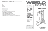
Weslo 750 Instruction Manual - Page 6
Adjustments
 |
View all Weslo 750 manuals
Add to My Manuals
Save this manual to your list of manuals |
Page 6 highlights
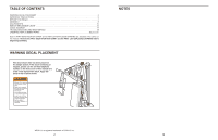
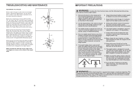
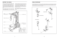
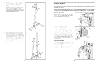
2. Attach the Upright (3) to the Base (1) with the two 2 M8 x 63mm Carriage Bolts (58) and two M8 Nylon Locknuts (69). Do not tighten the Locknuts. Attach the Press Frame Lock (39) to the Upright (3) with an M8 x 63mm Bolt (66), two M8 Washers (71), and an M8 Nylon Locknut (69). Do not overtighten the Locknut; the Press Frame Lock must be able to pivot easily. 39 66 71 69 71 3 3. Set two Weight Bumpers (17) over the indicated 3 holes in the Stabiliser (2). Insert two Weight Guides (10) into the same holes. Make sure that the indicated holes are closer to the bottom of the Weight Guides. Secure the Weight Guides in place with two M10 x 70mm Bolts (57), two M10 Washers (70), two 10mm x 12.5mm Spacers (37), and two M10 Nylon Locknuts (68). Tighten the M10 Nylon Locknuts (68) used in steps 1 and 3. 69 1 58 10 Holes 17 70 57 68 37 68 2 6 ADJUSTMENTS This section explains how to adjust the weight system. Refer to the accompanying exercise guide to see the correct form for each exercise. Make sure all parts are properly tightened each time the weight system is used. Replace any worn parts immediately. The weight system can be cleaned with a damp cloth and a mild, non-abrasive detergent. Do not use solvents. ATTACHING THE LAT BAR Attach the Lat Bar (31) to the High Cable (50) with a 50 Cable Clip (33). Remove the Lat Bar when perform- ing an exercise that does not require it. 33 31 CHANGING THE WEIGHT SETTING To change the weight setting, insert a Weight Pin (16) under the desired Weight (15) until the bent end of the Weight Pin is touching the Weights. Turn the bent end downward. The weight setting of each weight stack can be changed from 6 pounds to 106 pounds, in 12.5-pound increments. Note: Due to the cables and pulleys, the amount of resistance at each exercise station may vary from the weight setting. Use the WEIGHT RESISTANCE CHART on page 16 to find the approximate amount of resistance at each weight station. CONVERTING THE ARMS To use the Arms (6, 7) as butterfly arms, remove the "L"-pins (30), and engage the Press Frame Lock (39) into the Press Frame (5). To use the Arms (6, 7) as press arms, disengage the Press Frame Lock (39), and insert the "L"-pins (30) into the holes in the Press Frame (5) and Arms. 16 15 30 39 6 5 7 15
-
 1
1 -
 2
2 -
 3
3 -
 4
4 -
 5
5 -
 6
6 -
 7
7 -
 8
8 -
 9
9 -
 10
10 -
 11
11 -
 12
12
 |
 |
