Weslo Pursuit E45 Bike English Manual - Page 6
Firmly, Make sure, that the wires and cables are not pinched.
 |
View all Weslo Pursuit E45 Bike manuals
Add to My Manuals
Save this manual to your list of manuals |
Page 6 highlights
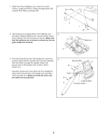
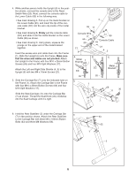
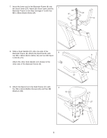
4. While another person holds the Upright (6) in the position shown, connect the console wire to the Reed Switch Wire (20). Next, connect the console cable to the Lower Cable (65) in the following way: • See inset drawing A. Pull up on the metal bracket on the Lower Cable (65), and insert the tip of the console cable (CC) into the wire clip inside of the metal bracket. • See inset drawing B. Firmly pull the console cable (CC) and slide it into the metal bracket on the Lower Cable (65) as shown. • See inset drawing C. Using pliers, squeeze the prongs on the upper end of the metal bracket together. Insert the excess wire and cable down into the Frame (1). Slide the Upright (6) onto the Frame. Make sure that the wires and cables are not pinched. Attach the Upright to the Frame with four M10 x 25mm Button Screws (69) and four M10 Split Washers (17). Attach the Left and Right Side Shields (4, 5) to the Upright (6) with two M4 x 16mm Screws (21). 5. Slide the Carriage Bar (7) onto the indicated tube on the Frame (1). Attach the Carriage Bar to the Frame with four M10 x 25mm Button Screws (69) and four M10 Split Washers (17). Slide the Seat Carriage (11) onto the Carriage Bar (7) as shown. Thread the Seat Knob (30) clockwise into the Seat Carriage until it is tight. 4 6 69 17 Console Wire 17 69 20 1 21 17 69 Console Cable 65 21 45 A Metal Bracket CC 65 5 B CC 65 1 17 C Metal Bracket 69 30 11 69 7 6. Hold the Rear Stabilizer (3) under the Carriage Bar 6 (7) in the position shown. Attach the Rear Stabilizer to the Carriage Bar with three M8 x 100mm Button Bolts (63) and three M8 Washers (55). 63 63 55 55 7 3 6
-
 1
1 -
 2
2 -
 3
3 -
 4
4 -
 5
5 -
 6
6 -
 7
7 -
 8
8 -
 9
9 -
 10
10 -
 11
11 -
 12
12 -
13
-
14
-
15
-
16
 |
 |
