Whirlpool EL88TRRW Installation Instructions - Page 3
Installation Requirements
 |
View all Whirlpool EL88TRRW manuals
Add to My Manuals
Save this manual to your list of manuals |
Page 3 highlights
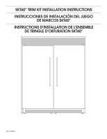
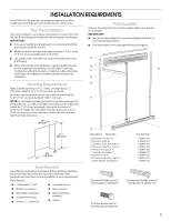
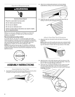
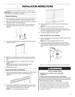
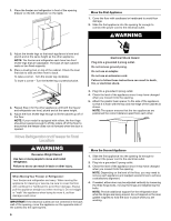
INSTALLATION REQUIREMENTS The SKT60* Trim Kit provides an integrated appearance when installing an all-refrigerator and upright freezer side by side. Plan the Installation Plan your installation using these instructions in conjunction with the Use & Care Guides provided with the refrigerator and freezer. IMPORTANT: For ease in handling and alignment, it is recommended that two people install the trim kit. Make sure there is enough area, approximately 7 ft (2.1 m) by 10 ft (3.1 m) to assemble parts on the r. Lay a drop cloth on the the to cushion the parts and cover These instructions are intended as a general guide only and do not supersede any national or local codes in any way. Compliance with all local, state or national codes pertaining to this type of installation should be determined prior to installation. Parts Supplied Remove the parts from the trim kit package. Make sure all parts are included. IMPORTANT: Do not use sharp objects to remove packaging materials to avoid scratching surfaces. The metal parts can be damaged if they are dropped. A B C H D Opening Requirements Make sure the opening is 74 ¹⁄ " (189.2 cm) high by 62 " (157.8 cm) wide by 24 " (61.6 cm) deep, as shown. The inner opening dimensions of the installed trim kit will be 61.31" (155.7 cm) wide by 66.85" (189.7 cm) high. NOTE: It is possible to make the trim kit t vertical openings that are less than 74 " (189.2 cm) high. The trim kit can be reduced in height by 1" (2.54 cm) increments. Each grille extrusion is 1" (2.54 cm) in height. For each grille extrusion that is not used, 1" (2.54 cm) must be cut from the base of both the left hand and right hand side extrusions. 24¹⁄ " (61.6 cm) 74¹⁄ " (189.2 cm) 62¹⁄ " (157.8 cm) E F G Description (Quantity) A. Extrusion, Top Trim (1) B. Extrusion, Grille (6) C Extrusion Grille-Notched (1) D. Extrusion, Side Trim - Left (1) E. Plastic Foam Spacer (1) F. Gap Filler Assembly (1) G. Bracket, Front (1) H. Extrusion, Side Trim - Right (1) I. Grille, Bottom Assembly (1) I Part Number 3-82842-001 3-82840-001 3-82840-002 3-82841-001 3-82841-002 4-82968-001 3-82967-001 2-82975-001 2-82984-001 Tools Needed Assemble the required tools and parts before starting installation. Read and follow the instructions provided with any of the required tools listed here. Proper installation is your responsibility. Tools Needed: Cordless drill, " bit Carpenter's level Phillips screwdriver Tape measure Flat-blade screwdriver Socket drive #2 bits Ratchet " socket bit Tape (masking or painters) Glasses Pan head Phillips screw (7) Part Number 3-24004-091 Countersunk Phillips screw (2) Part Number 3-24004-159 5/16 Hex Head screw (4) Part Number W10204670 3
-
 1
1 -
 2
2 -
 3
3 -
 4
4 -
 5
5 -
 6
6 -
 7
7 -
 8
8 -
 9
9 -
10
-
11
-
12
-
13
-
14
-
15
-
16
-
17
-
18
-
19
-
20
 |
 |
