Whirlpool WFG975H0H Installation Instructions
Whirlpool WFG975H0H Manual
 |
View all Whirlpool WFG975H0H manuals
Add to My Manuals
Save this manual to your list of manuals |
Whirlpool WFG975H0H manual content summary:
- Whirlpool WFG975H0H | Installation Instructions - Page 1
2 INSTALLATION REQUIREMENTS 3 Tools and Parts 3 Location Requirements 4 Electrical Requirements 5 Gas Supply Requirements 6 INSTALLATION INSTRUCTIONS 7 Unpack Range 7 Install Anti-Tip Bracket 8 Make Gas Connection 8 Install Griddle 10 Verify Anti-Tip Bracket Is Installed and Engaged - Whirlpool WFG975H0H | Installation Instructions - Page 2
call your gas supplier from a neighbor's phone. Follow the gas supplier's instructions. • If you cannot reach your gas supplier, call the fire department. - Installation and service must be performed by a qualified installer, service agency or the gas supplier. WARNING: Gas leaks cannot always be - Whirlpool WFG975H0H | Installation Instructions - Page 3
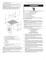
foot is engaged in the slot of the anti-tip bracket. Re-engage anti-tip bracket if range is moved. Do not operate range without anti-tip bracket installed and engaged. Failure to follow these instructions can result in death or serious burns to children and adults. Anti-Tip Bracket To verify the - Whirlpool WFG975H0H | Installation Instructions - Page 4
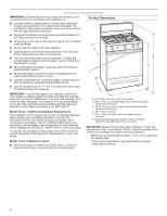
standards CAN/CSA-Z240, latest edition, or with local codes. Mobile home installations require: ■ When this range is installed in a mobile home, it must be secured according to the instructions in this document. E D A. 273/8" (69.5 cm) max. depth with handle B. 46¹⁄2" (118.1 cm) overall height (max - Whirlpool WFG975H0H | Installation Instructions - Page 5
not remove ground prong. Do not use an adapter. Do not use an extension cord. Failure to follow these instructions can result in death, fire, or electrical shock. IMPORTANT: The range must be electrically grounded in accordance with local codes and ordinances, or in the absence of local codes, with - Whirlpool WFG975H0H | Installation Instructions - Page 6
range must be conducted according to the manufacturer's instructions. Type of Gas Natural Gas: ■ This range Conversion must be done by a qualified service technician. No attempt shall be made to ■ Must include a shut-off valve: Install a manual gas line shut-off valve in an easily accessible location - Whirlpool WFG975H0H | Installation Instructions - Page 7
from the gas supply piping system by closing its individual manual shut-off valve during any pressure testing of the gas supply piping system at test pressures equal to or less than 1/2 psi (3.5 kPa). INSTALLATION INSTRUCTIONS Unpack Range WARNING Excessive Weight Hazard Use two or more people to - Whirlpool WFG975H0H | Installation Instructions - Page 8
tip the range and be killed. Install anti-tip bracket to floor or wall per installation instructions. Slide range back so rear range foot is engaged : licensed heating personnel, authorized gas company personnel, and authorized service personnel. Failure to do so can result in death, explosion - Whirlpool WFG975H0H | Installation Instructions - Page 9
2. Using a pipe wrench to tighten, connect the gas supply to the range. A B A. Gas pressure regulator B. 90° elbow (must have 1/2" (1.3 cm) male pipe thread) C. Nipple D. Union E. Black iron pipe F. Manual gas shut-off valve G. 1/2" (1.3 cm) or 3/4" (1.9 cm) gas pipe H. Nipple I. Union J. 90° - Whirlpool WFG975H0H | Installation Instructions - Page 10
Clean the griddle before using. Refer to the Use and Care Guide for cleaning instructions. The griddle can be placed over the left, right, Failure to follow these instructions can result in death, fire, or electrical shock. 7. Plug into a grounded 3 prong outlet. 8. Slide range into final location, - Whirlpool WFG975H0H | Installation Instructions - Page 11
anti-tip bracket installed and engaged. Please refer "Warranty" to contact service. Level Range Determine if you have AquaLift®† Technology or Steam Clean by referring to the "Range Care" section of the User Instructions. For Ranges with AquaLift® Technology or Steam Clean: 1. Place level on the - Whirlpool WFG975H0H | Installation Instructions - Page 12
the "OFF" position. ■ Check that the range is plugged in. Check that the circuit breaker knobs to Off and contact your dealer or authorized service company for assistance. Check Operation of Oven Bake Refer to the Use and Care Guide or User Instructions for proper operation of the oven controls - Whirlpool WFG975H0H | Installation Instructions - Page 13
inside the warming drawer or premium storage drawer, and allow the range to cool completely before attempting to remove the drawer. To Remove: will try for 3 entire cycles. Refer to the Use and Care Guide or User Instructions for proper operation of the oven controls. Adjust Oven Broil Burner Flame - Whirlpool WFG975H0H | Installation Instructions - Page 14
off valve is in the "on" position. ■ Electrical supply is connected. ■ See "Troubleshooting" in the Use and Care Guide or User Instructions. 8. When the range has been on for 5 minutes, check for heat. If the range is cold, turn off the range and check that the gas supply line shut-off valve is open - Whirlpool WFG975H0H | Installation Instructions - Page 15
anti-tip bracket. Re-engage anti-tip bracket if range is moved. Do not operate range without anti-tip bracket installed and engaged. Failure to follow these instructions can result in death or serious burns to children and adults. 1. Turn the manual shut-off valve to the closed position. B A C A. To - Whirlpool WFG975H0H | Installation Instructions - Page 16
3. Remove plastic cover from gas pressure regulator cap. 4. Turn gas pressure regulator cap counterclockwise with a 5/8" (1.6 cm) combination wrench to remove. NOTE: Do not remove the spring beneath the cap. Side view before A 3. Apply masking tape to the end of a 9/32" (7 mm) nut driver to help - Whirlpool WFG975H0H | Installation Instructions - Page 17
To Convert Oven Bake Burner (Natural Gas to Propane Gas) 1. Remove the oven racks and the oven door. See the "Oven Door" section. 2. Remove two screws and washers at the rear of the oven bottom. 3. Lift the rear of the oven bottom up and back until the front of the panel is away from the front frame - Whirlpool WFG975H0H | Installation Instructions - Page 18
anti-tip bracket. Re-engage anti-tip bracket if range is moved. Do not operate range without anti-tip bracket installed and engaged. Failure to follow these instructions can result in death or serious burns to children and adults. 1. Turn the manual shut-off valve to the closed position. B A C A. To - Whirlpool WFG975H0H | Installation Instructions - Page 19
3. Remove plastic cover from gas pressure regulator cap. 4. Turn gas pressure regulator cap counterclockwise with a 5/8" (1.6 cm) combination wrench to remove. NOTE: Do not remove the spring beneath the cap. Side view before A LP 3. Apply masking tape to the end of a 9/32" (7 mm) nut driver to - Whirlpool WFG975H0H | Installation Instructions - Page 20
3. Lift the rear of the oven bottom up and back until the front of the panel is away from the front frame. Remove from oven and set it aside on a covered surface. A B 6. Apply masking tape to the end of a 3/8" (9.5 mm) nut driver to help hold the gas orifice spud in the nut driver while changing it - Whirlpool WFG975H0H | Installation Instructions - Page 21
Refer to the "Make Gas Connection" section for properly connecting the range to the gas supply. 2. Refer to the "Electronic Ignition System" tips. 3. Refer to "Complete Installation" in the "Installation Instructions" section of these instructions to complete this procedure. NOTE: Make sure to save - Whirlpool WFG975H0H | Installation Instructions - Page 22
entretien doivent être effectués par un installateur qualifié, une agence de service ou le fournisseur de gaz. AVERTISSEMENT : L'odorat ne permet pas gaz local. En cas de détection d'une fuite de gaz, exécuter les instructions "Que faire dans le cas d'une odeur de gaz". IMPORTANT : Ne pas installer - Whirlpool WFG975H0H | Installation Instructions - Page 23
Fixer la bride antibasculement au plancher ou au mur, conformément aux instructions d'installation. Faire glisser de nouveau la cuisinière de façon à antibasculement n'est pas installée et engagée. Le non-respect de ces instructions peut causer un décès ou des brûlures graves aux enfants et aux - Whirlpool WFG975H0H | Installation Instructions - Page 24
revêtement de sol qualifié de vérifier que le revêtement de plancher peut supporter une température de 200 °F (93 °C). ■ Dans le cas de l'installation : La cuisinière doit être d'aplomb après l'installation. Suivre les instructions de la section « Ajustement de l'aplomb de la cuisinière ». Il - Whirlpool WFG975H0H | Installation Instructions - Page 25
pas enlever la broche de liaison à la terre. Ne pas utiliser un adaptateur. Ne pas utiliser un câble de rallonge. Le non-respect de ces instructions peut causer un décès, un incendie ou un choc électrique. IMPORTANT : La cuisinière doit être reliée à la terre en conformité avec les codes et - Whirlpool WFG975H0H | Installation Instructions - Page 26
Fuel Gas Code ANSI Z223.1 ou CAN/CGA B149. IMPORTANT : Les tests de fuite de la cuisinière doivent être effectués selon les instructions du fabricant. Type de gaz Gaz naturel : ■ Cette cuisinière a été configurée à l'usine pour l'alimentation au gaz naturel. Voir la section « Conversions pour - Whirlpool WFG975H0H | Installation Instructions - Page 27
ère. Utiliser une clé ou une pince pour abaisser les pieds de nivellement avant et arrière d'un demi-tour. Le non-respect de cette instruction peut causer C une blessure au dos ou d'autre blessure. A 1. Ôter les matériaux d'emballage, le ruban adhésif et la pellicule protectrice de la cuisini - Whirlpool WFG975H0H | Installation Instructions - Page 28
Fixer la bride antibasculement au plancher ou au mur, conformément aux instructions d'installation. Faire glisser de nouveau la cuisinière de façon bride antibasculement n'est pas installée et engagée. Le non-respect de ces instructions peut causer un décès ou des brûlures graves aux enfants et aux - Whirlpool WFG975H0H | Installation Instructions - Page 29
du brûleur. A B C A A. Robinet d'arrêt du détendeur à la position « On » (ouvert) D E A. Chapeau de brûleur B. Ouverture du tube d'arrivée de gaz C. Base du brûleur D. Support d'injecteur E. Électrode d'allumage 29 - Whirlpool WFG975H0H | Installation Instructions - Page 30
sentée est générique, le produit actuel peut être différent. A B A. Pieds B. Avant 2. Nettoyer la plaque avant utilisation. Consulter le Guide d'utilisation et d'entretien pour obtenir les instructions de nettoyage. La grille peut être placée sur le brûleur de gauche, de droite ou du centre. Risque - Whirlpool WFG975H0H | Installation Instructions - Page 31
l'avant jusqu'à ce que le pied de nivellement arrière sorte de la bride antibasculement. 3. Suivre les instructions fournies pour le type 1 ou 2, en fonction du type de tiroir fourni avec la cuisinière. Pour Clean (nettoyage à la vapeur). †AQUALIFT® est une marque déposée de Whirlpool, É.-U. 31 - Whirlpool WFG975H0H | Installation Instructions - Page 32
tourner les boutons de commande sur Off (arrêt) et contacter le revendeur ou le service de maintenance agréé. 1. Ôter la grille du four. 2. Pour retirer la partie du four et du gril. Consulter le guide d'utilisation et d'entretien ou les Instructions d'utilisation pour connaître le bon - Whirlpool WFG975H0H | Installation Instructions - Page 33
fait une pause de 40 secondes, puis tente un nouvel allumage pendant 8 secondes. Il essaiera 3 fois de suite. Consulter le guide d'utilisation et d'entretien ou les Instructions d'utilisation pour connaître le bon fonctionnement des commandes du four. Réglage de la taille des flammes sur le brûleur - Whirlpool WFG975H0H | Installation Instructions - Page 34
un électricien qualifié. Pour obtenir de l'assistance ou une visite de service : Consulter la section « Assistance ou service » du guide d'utilisation et d'entretien, la couverture des instructions d'utilisation ou contacter le service à la clientèle. 2. Ouvrir la porte du four. On devrait entendre - Whirlpool WFG975H0H | Installation Instructions - Page 35
la bride antibasculement au plancher ou au mur, conformément aux instructions d'installation. Faire glisser de nouveau la cuisinière de faç bride antibasculement n'est pas installée et engagée. Le non-respect de ces instructions peut causer un décès ou des brûlures graves aux enfants et aux adultes - Whirlpool WFG975H0H | Installation Instructions - Page 36
de brûleur B. Base du brûleur C. Tiges d'alignement D. Électrode d'allumage E. Ouverture du tube d'arrivée de gaz A. Électrode d'allumage B. Injecteur C. Support d'injecteur D. Vis 4. Retirer les injecteurs fournis dans le sachet de documentation situé dans le four. Chaque injecteur est marqué d'un - Whirlpool WFG975H0H | Installation Instructions - Page 37
Conversion du brûleur de cuisson au four (du gaz naturel au gaz propane) 1. Retirer les grilles et la porte du four. Voir la section « Porte du four ». 2. Ôter 2 vis et rondelles à l'arrière de la partie inférieure du four. 3. Soulever l'arrière de la base du four et la pousser vers l'arrière jusqu - Whirlpool WFG975H0H | Installation Instructions - Page 38
la bride antibasculement au plancher ou au mur, conformément aux instructions d'installation. Faire glisser de nouveau la cuisinière de faç bride antibasculement n'est pas installée et engagée. Le non-respect de ces instructions peut causer un décès ou des brûlures graves aux enfants et aux adultes - Whirlpool WFG975H0H | Installation Instructions - Page 39
de brûleur B. Base du brûleur C. Tiges d'alignement D. Électrode d'allumage E. Ouverture du tube d'arrivée de gaz A. Électrode d'allumage B. Injecteur C. Support d'injecteur D. Vis 4. Chaque injecteur est marqué d'un code d'identification gravé sur le côté ou le dessus. Remplacer le gicleur pour - Whirlpool WFG975H0H | Installation Instructions - Page 40
3. Soulever l'arrière de la base du four et la pousser vers l'arrière jusqu'à ce que l'avant du panneau ne soit plus près du cadre avant. Le retirer du four et le mettre de côté sur une surface couverte. A B 6. Appliquer du ruban adhésif de masquage à l'extrémité d'un tourne-écrou de 3/8 po (9,5 mm - Whirlpool WFG975H0H | Installation Instructions - Page 41
. Les flammes d'un brûleur alimenté au gaz naturel ne comportent pas de pointes jaunes. 3. Voir la section « Achever l'installation » des « Instructions d'installation » de ce document pour achever cette procédure. REMARQUE : Conserver les gicleurs qui viennent d'être remplacés lors de la conversion - Whirlpool WFG975H0H | Installation Instructions - Page 42
SEGURIDAD DE LA ESTUFA Su seguridad y la seguridad de los demás es muy importante. Hemos incluido muchos mensajes importantes de seguridad en este manual y en su electrodoméstico. Lea y obedezca siempre todos los mensajes de seguridad. Este es el símbolo de alerta de seguridad. Este símbolo le llama - Whirlpool WFG975H0H | Installation Instructions - Page 43
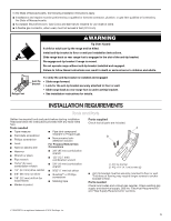
cualquiera de las herramientas detalladas aquí. Herramientas necesarias ■ Cinta métrica ■ Destornillador de cabeza plana ■ Destornillador Phillips ■ Nivel ■ Taladro manual o eléctrico ■ Compuesto para unión de tuberías resistente a gas propano ■ Solución para detectar fugas no corrosiva Para las - Whirlpool WFG975H0H | Installation Instructions - Page 44
Requisitos de ubicación IMPORTANTE: Respete todos los códigos y las ordenanzas vigentes. No obstruya el flujo de aire para la combustión y la ventilación. Dimensiones del producto ■ Es responsabilidad del instalador cumplir con los espacios de instalación especificados en la placa que indica - Whirlpool WFG975H0H | Installation Instructions - Page 45
Dimensiones del gabinete Las dimensiones de abertura del armario que se muestran son para una profundidad de mostrador de 25" (64,0 cm), una profundidad del armario de la base de 24" (61,0 cm) y una altura del mostrador de 36" (91,4 cm). IMPORTANTE: Si va a instalar una campana para estufa o una - Whirlpool WFG975H0H | Installation Instructions - Page 46
ía que sean resistentes a la acción del gas propano. No utilice 46 cinta de TEFLON®†. ■ Debe incluir una válvula de cierre: Instale una válvula de cierre manual para líneas de gas en un lugar de fácil acceso. No bloquee el acceso a la válvula de cierre. La válvula es para abrir o cerrar el - Whirlpool WFG975H0H | Installation Instructions - Page 47
). Prueba de presión de la línea a 1/2 psi (3,5 kPa) de manómetro 14" (35,6 cm) de WCP o menos Se debe cerrar la válvula de cierre individual manual para aislar la estufa del sistema de tubería de suministro de gas durante cualquier prueba de presión efectuada en el sistema con presiones de prueba - Whirlpool WFG975H0H | Installation Instructions - Page 48
Instalación del soporte antivuelco ADVERTENCIA Montaje en la pared Peligro de Vuelco Un niño o un adulto puede volcar accidentalmente la estufa y resultar muerto. Instale el soporte anti-vuelco al piso o a la pared según las instrucciones de instalación. Deslice la estufa hacia atrás de modo que - Whirlpool WFG975H0H | Installation Instructions - Page 49
de 90° (debe tener una rosca macho para tubería de 1/2" [1,3 cm]) C. Niple D. Unión E. Tubo de hierro negro F. Válvula de cierre de gas manual G. Tubo de gas de 1/2" (1,3 cm) o 3/4" (1,9 cm) H. Niple I. Unión J. Codo de 90° Conexión flexible típica 1. Aplique compuesto para unión de tuberías apto - Whirlpool WFG975H0H | Installation Instructions - Page 50
genérica; el producto real puede tener una apariencia distinta. A B B A. Incorrecto B. Correcto A. Patas B. Frontal 2. Limpie la plancha antes de usarla. Consulte el Manual de uso y cuidado para ver las instrucciones de limpieza. La plancha se puede colocar sobre el quemador de la izquierda, de la - Whirlpool WFG975H0H | Installation Instructions - Page 51
un rendimiento satisfactorio del horneado y resultados óptimos de la limpieza con las funciones de tecnología AquaLift® y limpieza con vapor. †®AQUALIFT es una marca registrada de Whirlpool, U.S.A. 51 - Whirlpool WFG975H0H | Installation Instructions - Page 52
á durante 3 ciclos completos. Los encendedores electrónicos se usan para encender los quemadores de hornear y de asar a la parrilla. Consulte el Manual de uso y cuidado o las Instrucciones para el usuario para ver el funcionamiento correcto de los controles del horno. La llama puede regularse con - Whirlpool WFG975H0H | Installation Instructions - Page 53
del horno hará una pausa de 40 segundos y volverá a intentar encenderse durante otros 8 segundos. Esto se repetirá durante 3 ciclos completos. Consulte el Manual de uso y cuidado o las Instrucciones para el usuario para ver el funcionamiento correcto de los controles del horno. Cómo regular la llama - Whirlpool WFG975H0H | Installation Instructions - Page 54
de gas esté en la posición "on" ("Abierta"). ■ Que el suministro eléctrico esté conectado. ■ Vea la sección "Solución de problemas" del Manual de uso y cuidado o las Instrucciones del usuario. 8. Cuando la estufa haya estado encendida durante 5 minutos, verifique que haya calor. Si la estufa está fr - Whirlpool WFG975H0H | Installation Instructions - Page 55
instrucciones puede ocasionar la muerte o quemaduras graves en niños y adultos. 1. Lleve la válvula de cierre manual a la posición cerrada. B A C A. A la estufa B. Válvula de cierre manual en la posición cerrada C. Línea de suministro de gas 2. Desenchufe la estufa o desconecte el suministro el - Whirlpool WFG975H0H | Installation Instructions - Page 56
3. Retire la cubierta plástica de la tapa del regulador de presión de gas. 4. Gire la tapa del regulador de presión de gas en sentido antihorario con una llave de combinación de 5/8" (1,6 cm) para retirarla. NOTA: No quite el resorte que está debajo de la tapa. Vista lateral antes A NG 3. Aplique - Whirlpool WFG975H0H | Installation Instructions - Page 57
Para convertir el quemador de hornear del horno (de gas natural a gas propano) 1. Retire las parrillas del horno y la puerta del horno. Consulte la sección "Puerta del horno". 2. Retire los 2 tornillos con sus arandelas de la parte posterior del piso del horno. 3. Levante la parte posterior del piso - Whirlpool WFG975H0H | Installation Instructions - Page 58
gas propano tienen una punta de color ligeramente amarillo. 3. Consulte "Complete la instalación" en la sección "Instrucciones de instalación" de este manual para completar este procedimiento. NOTA: Asegúrese de revisar los orificios que han sido reemplazados en la conversión. Peligro de Vuelco Un - Whirlpool WFG975H0H | Installation Instructions - Page 59
3. Retire la cubierta plástica de la tapa del regulador de presión de gas. 4. Gire la tapa del regulador de presión de gas en sentido antihorario con una llave de combinación de 5/8" (1,6 cm) para retirarla. NOTA: No quite el resorte que está debajo de la tapa. Vista lateral antes A LP 3. Aplique - Whirlpool WFG975H0H | Installation Instructions - Page 60
3. Levante la parte posterior del piso del horno hacia atrás hasta que la parte frontal del panel esté fuera del marco frontal. Retire del horno y reserve sobre una superficie cubierta. A B 6. Aplique cinta adhesiva protectora al extremo de un sacatuercas de 3/8" (9,5 mm) para ayudar a mantener el - Whirlpool WFG975H0H | Installation Instructions - Page 61
. Las llamas de gas natural no tienen puntas amarillas. 3. Consulte "Complete la instalación" en la sección "Instrucciones de instalación" de este manual para completar este procedimiento. NOTA: Asegúrese de revisar los orificios que han sido reemplazados en la conversión. C A. Quemador para asar - Whirlpool WFG975H0H | Installation Instructions - Page 62
NOTA 62 - Whirlpool WFG975H0H | Installation Instructions - Page 63
NOTA 63 - Whirlpool WFG975H0H | Installation Instructions - Page 64
W11419196A ©2020 All rights reserved. Used under license in Canada. Tous droits réservés. Utilisé sous licence au Canada. Todos los derechos reservados. Usado bajo licencia en Canadá. 05/20
-
 1
1 -
 2
2 -
 3
3 -
 4
4 -
 5
5 -
 6
6 -
 7
7 -
8
-
9
-
10
-
11
-
12
-
13
-
14
-
15
-
16
-
17
-
18
-
19
-
20
-
21
-
22
-
23
-
24
-
25
-
26
-
27
-
28
-
29
-
30
-
31
-
32
-
33
-
34
-
35
-
36
-
37
-
38
-
39
-
40
-
41
-
42
-
43
-
44
-
45
-
46
-
47
-
48
-
49
-
50
-
51
-
52
-
53
-
54
-
55
-
56
-
57
-
58
-
59
-
60
-
61
-
62
-
63
-
64
 |
 |

INSTALLATION INSTRUCTIONS
30" (76.2 CM) FREESTANDING GAS RANGES
INSTRUCTIONS D’INSTALLATION POUR CUISINIÈRES
AU GAZ AUTOPORTANTES DE 30 PO (76,2 CM)
INSTRUCCIONES DE INSTALACIÓN DE ESTUFAS
AUTÓNOMAS A GAS DE 30" (76,2 CM)
W11419196A
IMPORTANT:
Installer:
Leave installation instructions with the homeowner.
Homeowner:
Keep installation instructions for future reference.
Table of Contents
RANGE SAFETY
.............................................................................
2
INSTALLATION REQUIREMENTS
.................................................
3
Tools and Parts
............................................................................
3
Location Requirements
................................................................
4
Electrical Requirements
...............................................................
5
Gas Supply Requirements
...........................................................
6
INSTALLATION INSTRUCTIONS
...................................................
7
Unpack Range
..............................................................................
7
Install Anti-Tip Bracket
.................................................................
8
Make Gas Connection
.................................................................
8
Install Griddle
.............................................................................
10
Verify Anti-Tip Bracket Is Installed and Engaged
......................
11
Level Range
................................................................................
11
Electronic Ignition System
.........................................................
12
Warming Drawer or Premium Storage Drawer
..........................
13
Oven Door
..................................................................................
14
Complete Installation
.................................................................
14
GAS CONVERSIONS
....................................................................
15
Propane Gas Conversion
..........................................................
15
Natural Gas Conversion
.............................................................
18
IMPORTANT :
Installateur :
Remettre les instructions d’installation au propriétaire.
Propriétaire :
Conserver les instructions d’installation pour référence ultérieure.
Table des matières
SÉCURITÉ DE LA CUISINIÈRE
...................................................
22
EXIGENCES D’INSTALLATION
...................................................
23
Outils et pièces
...........................................................................
23
Exigences d’emplacement
.........................................................
24
Spécifications électriques
..........................................................
25
Spécifications de l’alimentation en gaz
.....................................
25
INSTRUCTIONS D’INSTALLATION
............................................
27
Déballage de la cuisinière
..........................................................
27
Bride antibasculement
...............................................................
28
Raccordement au gaz
................................................................
28
Installation de la plaque à frire
...................................................
30
Vérifier que la bride antibasculement est bien installée
et engagée
..................................................................................
31
Réglage de l’aplomb de la cuisinière
.........................................
31
Système d’allumage électronique
.............................................
32
Tiroir-réchaud ou tiroir de remisage de qualité supérieure
.......
33
Porte du four
..............................................................................
34
Terminer l’installation
.................................................................
34
CONVERSIONS DE GAZ
..............................................................
35
Conversion pour l’alimentation au propane
..............................
35
Conversion au gaz naturel
.........................................................
38
IMPORTANTE:
Instalador:
Déjele las instrucciones de instalación al propietario.
Propietario:
Guarde las instrucciones de instalación para futuras consultas.
Tabla de contenidos
SEGURIDAD DE LA ESTUFA
.......................................................
42
REQUISITOS DE INSTALACIÓN
.................................................
43
Herramientas y piezas
................................................................
43
Requisitos de ubicación
.............................................................
44
Requisitos eléctricos
..................................................................
45
Requisitos del suministro de gas
...............................................
46
INSTRUCCIONES DE INSTALACIÓN
.........................................
47
Desembalaje de la estufa
...........................................................
47
Instalación del soporte antivuelco
.............................................
48
Conexión del suministro de gas
................................................
48
Instalación de la plancha
...........................................................
50
Verifique que el soporte antivuelco esté instalado
y enganchado
.............................................................................
51
Nivelación de la estufa
...............................................................
51
Sistema de encendido electrónico
............................................
52
Cajón de calentamiento o cajón de almacenamiento
premium
........................................................................................
53
Puerta del horno
.........................................................................
54
Finalización de la instalación
.....................................................
54
CONVERSIONES DE GAS
...........................................................
55
Conversión a gas propano
.........................................................
55
Conversión a gas natural
...........................................................
58