Xerox 1235/DX Service Guide - Page 117
Left paper tray guide assembly, Removing the lower plate assembly
 |
UPC - 042215474542
View all Xerox 1235/DX manuals
Add to My Manuals
Save this manual to your list of manuals |
Page 117 highlights
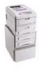
Left paper tray guide assembly Note Switch off the power and disconnect the power cord. 1. Remove the paper tray 1 from the printer. 2. Remove the duplexer unit if installed. 3. Remove the electrical chassis as described on "Electrical chassis (card cage)" on page 94 4. Remove the printer unit chassis as shown on page 97. 5. Remove the four screws securing the lower plate to the paper tray guide assemblies 6. Disconnect CN1 from the low voltage power supply. 7. Lift the lower plate and power supplies from the tray guides. Removing the lower plate assembly 104 Phaser 1235 Network Color Printer
-
 1
1 -
2
-
3
-
4
-
5
-
6
-
7
-
8
-
9
-
10
-
11
-
12
-
13
-
14
-
15
-
16
-
17
-
18
-
19
-
20
-
21
-
22
-
23
-
24
-
25
-
26
-
27
-
28
-
29
-
30
-
31
-
32
-
33
-
34
-
35
-
36
-
37
-
38
-
39
-
40
-
41
-
42
-
43
-
44
-
45
-
46
-
47
-
48
-
49
-
50
-
51
-
52
-
53
-
54
-
55
-
56
-
57
-
58
-
59
-
60
-
61
-
62
-
63
-
64
-
65
-
66
-
67
-
68
-
69
-
70
-
71
-
72
-
73
-
74
-
75
-
76
-
77
-
78
-
79
-
80
-
81
-
82
-
83
-
84
-
85
-
86
-
87
-
88
-
89
-
90
-
91
-
92
-
93
-
94
-
95
-
96
-
97
-
98
-
99
-
100
-
101
-
102
-
103
-
104
-
105
-
106
-
107
-
108
-
109
-
110
-
111
-
 112
112 -
 113
113 -
 114
114 -
 115
115 -
 116
116 -
 117
117 -
 118
118 -
 119
119 -
 120
120 -
 121
121 -
 122
122 -
123
-
124
-
125
-
126
-
127
-
128
-
129
-
130
-
131
-
132
-
133
-
134
-
135
-
136
-
137
-
138
-
139
-
140
-
141
-
142
-
143
-
144
-
145
-
146
-
147
-
148
-
149
-
150
-
151
-
152
-
153
-
154
-
155
-
156
-
157
-
158
-
159
-
160
-
161
-
162
-
163
-
164
-
165
-
166
-
167
-
168
-
169
-
170
-
171
-
172
-
173
-
174
-
175
-
176
-
177
-
178
-
179
-
180
-
181
-
182
-
183
-
184
-
185
-
186
-
187
-
188
-
189
-
190
-
191
-
192
-
193
-
194
-
195
-
196
-
197
-
198
-
199
-
200
-
201
-
202
-
203
-
204
-
205
-
206
-
207
-
208
-
209
-
210
-
211
-
212
-
213
-
214
-
215
-
216
-
217
-
218
-
219
-
220
-
221
-
222
-
223
-
224
-
225
-
226
-
227
-
228
-
229
-
230
-
231
-
232
-
233
-
234
-
235
-
236
-
237
-
238
-
239
 |
 |

104
Phaser 1235 Network Color Printer
Left paper tray guide assembly
Note
Switch off the power and disconnect the power cord.
1.
Remove the paper tray 1 from the printer.
2.
Remove the duplexer unit if installed.
3.
Remove the electrical chassis as described on “Electrical chassis (card
cage)” on page 94
4.
Remove the printer unit chassis as shown on page 97.
5.
Remove the four screws securing the lower plate to the paper tray
guide assemblies
6.
Disconnect CN1 from the low voltage power supply.
7.
Lift the lower plate and power supplies from the tray guides.
Removing the lower plate assembly