| Section |
Page |
| Important |
3 |
| Read the following before operating the CS1D |
3 |
| Handling the included PM1D System Software disc |
3 |
| CS1D Exclusion of Certain Responsibility |
4 |
| About the LCD display |
4 |
| Cautions when handling the track pad |
4 |
| Operating Manual (Start-up) |
6 |
| Contents |
7 |
| Introduction |
9 |
| About the “CS1D Operating Manual (Start-up)” |
9 |
| Printing conventions in “CS1D Operating Manual (Start-up)” |
9 |
| Introducing the various components |
10 |
| Terms used in the “CS1D Operating Manual (Start-up)” |
12 |
| Connections (Standard mode) |
14 |
| Connecting the console and engine (Standard mode) |
14 |
| Connecting an analog input/output unit to the engine (Standard mode) |
16 |
| Connecting a digital input/output unit to the engine (Standard mode) |
17 |
| Connections (Mirror mode) |
18 |
| Connecting the console and engines (Mirror mode) |
18 |
| Connecting an analog input/output unit to the engines (Mirror mode) |
20 |
| Connecting a digital input/output unit to the engines (Mirror mode) |
21 |
| Turning on the power and verifying the connections |
22 |
| Turning on the power |
22 |
| Checking the status of each device (Standard mode) |
23 |
| Checking the engine (Standard mode) |
23 |
| Checking the analog input unit (Standard mode) |
24 |
| Checking the analog output unit (Standard mode) |
25 |
| Digital input/output unit (Standard mode) |
25 |
| Checking the status of each device (Mirror mode) |
26 |
| Engines (Mirror mode) |
26 |
| Checking the analog input unit (Mirror mode) |
27 |
| Checking the analog output unit (Mirror mode) |
28 |
| Checking the digital input/output unit (Mirror mode) |
29 |
| Basic settings (Standard mode) |
30 |
| Selecting the operation mode (Standard mode) |
30 |
| Setting the word clock (Standard mode) |
32 |
| Basic settings (Mirror mode) |
34 |
| Selecting the operation mode (Mirror mode) |
34 |
| Setting the word clock (Mirror mode) |
36 |
| Checking the operation of input units |
38 |
| Preparations for checking |
38 |
| Connect the monitor system |
39 |
| Connect an input source |
40 |
| Patch the input unit to an input channel |
41 |
| Monitor the input signal |
44 |
| Checking the operation of an output unit |
46 |
| Preparations for checking |
46 |
| Connect the monitor system |
47 |
| Connect an input source |
48 |
| Patch the input unit to an input channel |
49 |
| Patch the STEREO A channel to an output unit |
50 |
| Send the input signals of input channels 1/2 to the STEREO bus |
52 |
| Turn off the power |
54 |
| Operating Manual (Basic Operation) |
55 |
| Contents |
56 |
| Chapter 1. Introduction |
60 |
| About the “CS1D Operation Manual (Basic Operation)” |
60 |
| Printing conventions in the “CS1D Operation Manual (Basic Operation)” |
60 |
| Overview of the PM1D system |
61 |
| Full-digital/separate type SR mixing system |
61 |
| Component structure |
61 |
| Signal flow in the PM1D system |
63 |
| Number of inputs/outputs and channel structure |
65 |
| MIX buses/MATRIX buses |
67 |
| Scene memories/Libraries |
67 |
| Word clock synchronization |
67 |
| Chapter 2. The user interfaces of the CS1D |
68 |
| About the user interfaces |
68 |
| User interfaces within the display |
68 |
| User interface on the top panel of the CS1D |
70 |
| External user interfaces |
71 |
| Various basic operations |
73 |
| Click |
73 |
| Drag |
73 |
| Drag and drop |
74 |
| Scroll |
74 |
| Accessing the desired screen |
75 |
| Button operations |
76 |
| Moving the cursor |
77 |
| Adjusting the value of a knob or fader |
78 |
| Assigning a name |
79 |
| Chapter 3. Audio connections and patching |
81 |
| Audio connections |
81 |
| Audio connections for an analog input unit |
81 |
| Audio connections for an analog output unit |
83 |
| Audio connections for a digital input/output unit |
84 |
| Audio connections for the console |
85 |
| Patching |
87 |
| Input channel patching |
87 |
| Output channel patching |
89 |
| Chapter 4. Basic operation for input channels |
91 |
| About input channels |
91 |
| Blocks used to control input channels |
91 |
| Changing the channel assignments |
92 |
| Basic operation INPUT blocks/ST IN block |
93 |
| INPUT block/ST IN block controls and functions |
93 |
| Head amp settings |
95 |
| Sending a signal from an input channel to a STEREO bus |
97 |
| Sending a signal from an input channel to a MIX bus |
98 |
| Pairing settings |
102 |
| Basic operation in the SELECTED INPUT CHANNEL block |
103 |
| Controls and functions of the SELECTED INPUT CHANNEL block |
103 |
| Head amp settings |
105 |
| Sending signals from an input channel to the STEREO bus |
106 |
| Sending signals from an input channel to a MIX bus |
108 |
| Using the delay |
110 |
| Using the compressor |
111 |
| Using the noise gate |
114 |
| Using the 4 band EQ/HPF |
116 |
| Chapter 5. Basic operation for output channels |
118 |
| About the output channels |
118 |
| Blocks used to control the output channels |
118 |
| Switching the channel assignments |
119 |
| Basic operation of the MIX OUTPUT block |
120 |
| Controls and functions of the MIX OUTPUT block |
120 |
| Sending a signal from a MIX channel to an output unit |
121 |
| Sending a signal from a MIX channel to a MATRIX bus |
122 |
| Sending a signal from a MIX channel to the STEREO bus |
124 |
| Pairing MIX channels |
125 |
| Basic operation of the MATRIX OUTPUT block |
128 |
| Controls and functions of the MATRIX OUTPUT block |
128 |
| Sending a signal from a MATRIX channel to an output unit |
128 |
| Pairing MATRIX channels |
129 |
| Basic operation of the STEREO OUTPUT block |
131 |
| Controls and functions of the STEREO OUTPUT block |
131 |
| Sending a signal from a STEREO A/B channel to an output unit |
132 |
| Basic operation of the SELECTED OUTPUT CHANNEL block |
133 |
| Controls and functions of the SELECTED OUTPUT CHANNEL block |
133 |
| Sending a signal from an output channel to an output unit |
134 |
| Sending a signal from a MIX channel to a MATRIX bus/STEREO bus |
136 |
| Sending a signal from the STEREO A channel to the MATRIX bus |
138 |
| Delay settings |
139 |
| Compressor settings |
140 |
| 6 band EQ/HPF settings |
142 |
| Chapter 6. Insert and direct out |
144 |
| Insert |
144 |
| Connecting the external device to be inserted |
144 |
| Inserting into an input channel |
145 |
| Inserting into an output channel |
148 |
| Direct out |
150 |
| Direct out connections |
150 |
| Directly outputting an input channel signal |
150 |
| Chapter 7. DCA groups/Mute groups |
152 |
| DCA groups |
152 |
| Assigning a channel to a DCA group |
152 |
| Controlling a DCA group |
154 |
| Mute groups |
155 |
| Assigning input channels to a mute group |
155 |
| Assigning output channels to a mute group |
156 |
| Controlling a mute group |
157 |
| Chapter 8. Scene memory |
159 |
| About scenes |
159 |
| Scene memory operations |
161 |
| Storing a scene |
161 |
| Recalling a scene |
162 |
| Using PREVIEW mode |
163 |
| Directly recalling a scene |
164 |
| Chapter 9. Recall safe/Mute safe |
165 |
| Recall safe |
165 |
| Using the console to set/defeat Recall Safe |
165 |
| Using the screen to set/defeat Recall Safe |
166 |
| Mute safe |
167 |
| Using the console to set/defeat Mute Safe |
167 |
| Using the screen to set/defeat Mute Safe |
168 |
| Chapter 10. Monitor |
169 |
| Basic operation of the MONITOR A/MONITOR B section |
169 |
| About MONITOR A/MONITOR B |
169 |
| Controls and functions of the MONITOR A/MONITOR B sections |
170 |
| Using the MONITOR A section to monitor a signal |
170 |
| Using the MONITOR B section to monitor a signal |
172 |
| Using the Cue/Solo function |
174 |
| Cue mode and Solo mode |
174 |
| Cue/Solo groups |
175 |
| Controls and functions of the CUE section |
176 |
| Using the Cue function |
176 |
| Using the Solo function |
178 |
| Chapter 11. Talkback/Oscillator |
179 |
| Talkback |
179 |
| Oscillator |
181 |
| Chapter 12. Internal effects |
183 |
| About the internal effects of the PM1D system |
183 |
| Patching an internal effect |
184 |
| Using an internal effect via the MIX bus |
184 |
| Inserting an internal effect into a channel |
187 |
| Basic operation of the effect screen |
189 |
| Editing effect parameters |
189 |
| Recalling effect data from the library |
190 |
| Storing effect data to the library |
192 |
| Chapter 13. Graphic EQ |
193 |
| Inserting a graphic EQ into a channel |
193 |
| Controlling a graphic EQ |
195 |
| Controlling a graphic EQ from the display |
195 |
| Controlling a graphic EQ from the DCA faders |
196 |
| Chapter 14. MIDI/Time Code |
198 |
| Using MIDI program changes to control events |
198 |
| Using time code to control events |
201 |
| Chapter 15. Using a memory card to save/load data |
203 |
| Saving a file onto a memory card |
203 |
| Loading a file from a memory card |
205 |
| Chapter 16. Various settings |
207 |
| Initial settings for the console |
207 |
| Setting the internal calendar and clock |
209 |
| Specifying the metering points |
210 |
| Input channel metering point |
210 |
| Output channel metering point |
211 |
| User defined function settings |
212 |
| Reference Manual (Hardware) |
215 |
| Contents |
216 |
| How the “CS1D Reference Manual (Hardware)” is organized |
218 |
| Printing conventions in the “CS1D Reference Manual (Hardware)” |
220 |
| INPUT block |
221 |
| INPUT block channel assignments |
222 |
| ST IN block |
229 |
| Channel assignments for the ST IN block |
230 |
| SELECTED INPUT CHANNEL block |
236 |
| +48/ø/INSERT (+48/phase/insert) section |
238 |
| INPUT section |
239 |
| DELAY section |
239 |
| MIX SEND section |
240 |
| COMPRESSOR section |
242 |
| NOISE GATE section |
244 |
| EQUALIZER section |
246 |
| STEREO section |
247 |
| GAIN section |
248 |
| ATTENUATOR section |
248 |
| FADER section |
249 |
| DCA section |
250 |
| SAFE section |
251 |
| CHANNEL SELECT section |
251 |
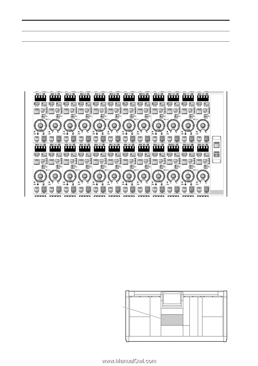
| GLOBAL CONTROL section |
253 |
| Display |
256 |
| MIX OUTPUT block |
257 |
| Channel assignments in the MIX OUTPUT block |
258 |
| MIX channel section |
259 |
| MIX LAYER section |
262 |
| MATRIX OUTPUT block |
263 |
| MATRIX OUTPUT block channel assignments |
264 |
| MATRIX channel section |
265 |
| MATRIX LAYER section |
268 |
| STEREO OUTPUT block |
269 |
| SELECTED OUTPUT CHANNEL block |
273 |
| DELAY section |
276 |
| COMPRESSOR section |
277 |
| EQUALIZER section |
279 |
| OUTPUT section |
280 |
| DCA section |
282 |
| SAFE section |
283 |
| CHANNEL SELECT section |
283 |
| DCA GROUP block |
286 |
| Select the items you wish to control from the DCA faders |
287 |
| DCA fader section |
288 |
| FADER STATUS section |
290 |
| MASTER block |
294 |
| TALKBACK section |
295 |
| OSCILLATOR section |
296 |
| Card slot section |
297 |
| CUE section |
298 |
| MONITOR A section |
300 |
| MONITOR B section |
302 |
| ENGINE section |
304 |
| GLOBAL LAYER section |
304 |
| METER section |
305 |
| SCENE MEMORY block |
306 |
| LCD FUNCTION ACCESS/USER DEFINE block |
313 |
| LCD ACCESS GLOBAL section |
314 |
| LCD ACCESS OUTPUT section |
314 |
| LCD ACCESS INPUT section |
315 |
| USER DEFINE |
315 |
| Data entry block |
316 |
| Meter bridge block |
318 |
| Meter section (left) |
319 |
| Meter section (right) |
319 |
| TIME CODE section |
320 |
| SCENE MEMORY section |
320 |
| Rear panel block |
321 |
| DIGITAL I/O section |
322 |
| 2-TRACK IN DIGITAL section |
323 |
| STEREO OUT DIGITAL section |
323 |
| WORD CLOCK section |
324 |
| LAMP connectors |
324 |
| 2-TRACK IN ANALOG section |
325 |
| MONITOR OUT ANALOG section |
325 |
| TALKBACK IN 2 section |
326 |
| CUE OUT ANALOG section |
326 |
| DC POWER section |
327 |
| CONTROL section 1 |
328 |
| CONTROL section 2 |
329 |
| Input/output signal flow |
330 |
| Front panel block |
331 |
| Reference Manual (Software) |
332 |
| Contents |
333 |
| How the “CS1D Reference Manual (Software)” is organized |
336 |
| Printing conventions in the “CS1D Reference Manual (Software)” |
336 |
| Information shown in the display |
337 |
| Function menu |
341 |
| Global functions |
344 |
| EFFECT functions |
344 |
| EFFECT 1–EFFECT 8 |
344 |
| EFFECT ASSIGN |
347 |
| GEQ (graphic EQ) functions |
348 |
| GEQ PARAMETER |
348 |
| GEQ ASSIGN 1-12/13-24 (graphic EQ assign 1–12/13–24) |
351 |
| SCENE functions |
353 |
| MEMORY |
353 |
| RECALL SAFE |
358 |
| FADE TIME |
360 |
| DIRECT RECALL |
362 |
| MIDI/GPI/TC function |
364 |
| MIDI PROGRAM (MIDI program change) |
364 |
| TC EVENT (time code event) |
368 |
| UTILITY functions |
371 |
| PREFERENCE |
371 |
| USER DEFINE |
373 |
| LOAD/SAVE |
375 |
| SYS/W.CLOCK (system/word clock) function |
379 |
| SYSTEM CONNECTION |
379 |
| INPUT UNIT |
382 |
| OUTPUT UNIT |
385 |
| WORD CLOCK |
388 |
| DITHER |
391 |
| METER functions |
393 |
| Input metering |
393 |
| Output metering |
395 |
| MON/CUE (monitor/cue) functions |
397 |
| TALKBACK |
397 |
| OSCILLATOR |
399 |
| 2TR IN (2 track in) |
402 |
| ST OUT DIGITAL (stereo out digital) |
403 |
| MONITOR A |
404 |
| MONITOR B |
407 |
| CUE/SOLO |
409 |
| Output functions |
411 |
| OUT PATCH (output patch) functions |
411 |
| OUTPUT PATCH |
411 |
| INSERT PATCH |
413 |
| INSERT POINT |
415 |
| INSERT VIEW |
416 |
| NAME |
418 |
| OUT INSERT (output insert) function |
421 |
| MIX 1-24 INS / MIX 25-48 INS / MATRIX 1-24 INS / ST MAS INS/UNIT LIB |
421 |
| OUT EQ (output equalizer) function |
424 |
| EQ PARAMETER |
424 |
| MIX 1-24/MIX 25-48/MATRIX 1-24/STEREO A, B |
426 |
| OUT COMP (output compressor) function |
428 |
| COMP PRM (compressor parameters) |
428 |
| MIX 1-12 – MIX 37-48/MATRIX 1-12 – MATRIX 13-24/STEREO A, B |
431 |
| OUT DELAY (output delay) function |
434 |
| MIX 1-24 /MIX 25-48/MATRIX 1-24/STEREO A, B |
434 |
| OUT DCA/MUTE (output DCA/mute) function |
436 |
| DCA ASSIGN |
436 |
| MUTE GROUP ASSIGN |
438 |
| MATRIX/ST (matrix/stereo) function |
440 |
| MATRIX/ST ROUTING (matrix/stereo routing) |
440 |
| MIX to MATRIX |
443 |
| SUB IN |
445 |
| LCR |
447 |
| OUT CH VIEW (output channel view) function |
449 |
| CH VIEW (channel view) |
449 |
| Input functions |
453 |
| IN PATCH functions |
453 |
| INPUT PATCH |
453 |
| DIRECT OUT PATCH |
455 |
| INSERT PATCH |
457 |
| INSERT/DIRECT POINT |
459 |
| INSERT/DIRECT VIEW |
461 |
| NAME |
463 |
| IN HA/INSERT (Input head amp/insert) functions |
466 |
| CH 1-24 – CH 73-96�/�ST IN 1-8�/�CH 1-24 INS – CH 73-96 INS�/�ST IN INS/UNIT LIB |
466 |
| IN EQ (Input equalizer) functions |
469 |
| EQ PARAMETER |
469 |
| CH 1-24 – CH 73-96/ST IN 1-8 |
472 |
| IN GATE/COMP function |
474 |
| GATE PRM (gate parameters) |
474 |
| COMP PRM (compressor parameters) |
477 |
| CH 1-12 – CH 85-96/ST IN 1-4 – ST IN 5-8 |
480 |
| IN DELAY functions |
483 |
| CH 1–24 – CH 72-96/ST IN 1-8 |
483 |
| IN DCA/MUTE functions |
485 |
| DCA ASSIGN |
485 |
| MUTE GROUP ASSIGN |
487 |
| PAN/ROUTING function |
489 |
| CH to MIX (channel to mix) |
489 |
| LCR |
495 |
| IN CH VIEW (input channel view) function |
497 |
| CH VIEW (channel view) |
497 |
| Libraries |
501 |
| Basic library operation |
501 |
| UNIT LIBRARY |
505 |
| PATCH LIBRARY |
507 |
| NAME LIBRARY |
509 |
| INPUT EQ LIBRARY |
511 |
| OUTPUT EQ LIBRARY |
513 |
| INPUT GATE LIBRARY |
515 |
| INPUT COMP LIBRARY |
517 |
| OUTPUT COMP LIBRARY |
519 |
| INPUT CHANNEL LIBRARY |
521 |
| OUTPUT CHANNEL LIBRARY |
523 |
| EFFECT LIBRARY |
525 |
| GEQ LIBRARY |
527 |
| Other |
529 |
| Memory initialization |
529 |
| Reference Manual (Appendices) |
530 |
| Contents |
531 |
| Appendices |
533 |
| Preset EQ Program Parameters |
533 |
| ・ INPUT EQ LIBRARY |
533 |
| • OUTPUT EQ LIBRARY |
537 |
| Preset Dynamics Program Settings |
538 |
| • INPUT GATE LIBRARY |
538 |
| • INPUT COMP LIBRARY |
539 |
| • OUTPUT COMP LIBRARY |
542 |
| Compressor Types |
543 |
| COMP |
543 |
| EXPANDER |
545 |
| COMPANDER (HARD & SOFT) |
546 |
| Gate Types |
548 |
| GATE |
548 |
| DUCKING |
549 |
| Preset Effects Programs |
550 |
| • Basic effect programs |
550 |
| • Advanced reverb programs |
551 |
| Effects Parameters |
553 |
| • REVERB [Type: STEREO] |
553 |
| • EARLY REF. [Type: STEREO] |
553 |
| • GATE REVERB, REVERSE GATE [Type: STEREO] |
554 |
| • ECHO [Type: STEREO] |
555 |
| • CHORUS [Type: STEREO] |
555 |
| • FLANGE [Type: STEREO] |
556 |
| • SYMPHONIC [Type: STEREO] |
556 |
| • PHASER [Type: STEREO] |
557 |
| • AUTO PAN [Type: STEREO] |
557 |
| • TREMOLO [Type: STEREO] |
558 |
| • HQ. PITCH [Type: MIX] |
558 |
| • DUAL PITCH [Type: STEREO] |
559 |
| • REV + CHORUS [Type: MIX] |
559 |
| · REV -> CHORUS [Type: MIX] |
560 |
| • REV + FLANGE [Type: MIX] |
560 |
| · REV -> FLANGE [Type: MIX] |
561 |
| • REV + SYMPHONIC [Type: MIX] |
561 |
| · REV -> SYMPHONIC [Type: MIX] |
562 |
| · REV -> PAN [Type: MIX] |
562 |
| • DELAY + ER. [Type: MIX] |
563 |
| · DELAY -> ER. [Type: MIX] |
563 |
| • DELAY + REV [Type: MIX] |
564 |
| · DELAY -> REV [Type: MIX] |
564 |
| • AMP SIMULATE [Type: MIX] |
565 |
| • DYNA. FILTER [Type: STEREO] |
565 |
| • DYNA. FLANGE [Type: STEREO] |
565 |
| • DYNA. PHASER [Type: STEREO] |
566 |
| Scene Memory/Effect Library to Program Change Table |
567 |
| Channel library list |
576 |
| Parameters copied when pairing |
577 |
| MIDI Data Format |
579 |
| Warning Message |
580 |
| Error Message |
581 |
| About the PM1D system version checking function |
581 |
| Troubleshooting |
582 |
| General Specifications |
585 |
| Controls & Indicators |
592 |
| Analog Input Characteristics |
597 |
| Analog Output Characteristics |
597 |
| Digital Input & Output Characteristics |
598 |
| Pin Assignment DIGITAL I/O ENGINE A1, A2, B1, B2 (D-SUB Half Pitch Connector 68P) |
599 |
| Pin Assignment DIGITAL I/O CONSOLE 1, 2 (D-SUB Half Pitch Connector 68P) |
600 |
| Pin Assignment GPI (D-SUB Connector 25P) |
601 |
| Pin Assignment OUTPUT A,B,C (D-SUB Half Pitch Connector 68P) |
602 |
| Pin Assignment INPUT A,B (D-SUB Half Pitch Connector 68P) |
603 |
| Pin Assignment DIGITAL I/O INPUT 1-10 D-SUB Half Pitch Connector 68P) |
604 |
| Pin Assignment DIGITAL I/O OUTPUT 1-6 (D-SUB Half Pitch Connector 68P) |
605 |
| Pin Assignment DIGITAL I/O CASCADE IN (D-SUB Half Pitch Connector 68P) |
606 |
| Pin Assignment DIGITAL I/O CASCADE OUT (D-SUB Half Pitch Connector 68P) |
607 |
| Pin Assignment DIGITAL I/O CONSOLE 1,2 (D-SUB Half Pitch Connector 68P) |
608 |
| Pin Assignment CONTROL I/O REMOTE RS-422 D-SUB Connector 9P) |
609 |
| Pin Assignment CONTROL I/O GPI (D-SUB Connector 25P) |
609 |
| Accessories |
610 |
| Dimensions |
610 |
| Cards Specifications |
611 |
| • LMY2-ML |
611 |
| • LMY4-AD |
612 |
| • LMY4-DA |
613 |
| MIDI Implementation Chart |
615 |
| PM1D V2.0 System Block Diagram |
616 |

 1
1 252
252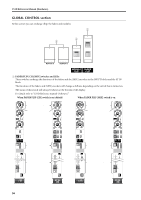 253
253 254
254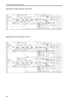 255
255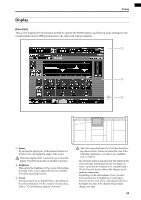 256
256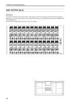 257
257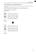 258
258 259
259 260
260 261
261 262
262