Yamaha MGP16X Owner's Manual
Yamaha MGP16X Manual
 |
View all Yamaha MGP16X manuals
Add to My Manuals
Save this manual to your list of manuals |
Yamaha MGP16X manual content summary:
- Yamaha MGP16X | Owner's Manual - Page 1
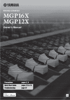
Owner's Manual Precautions Quick Start Guide Troubleshooting pages 4, 5 pages 12 to 14 page 27 EN - Yamaha MGP16X | Owner's Manual - Page 2
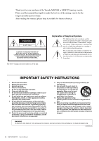
Thank you for your purchase of the Yamaha MGP16X or MGP12X mixing console. Please read this manual thoroughly to make the best use of the mixing console for the longest possible period of time. After reading this manual, please keep it available for future reference. CAUTION RISK OF ELECTRIC SHOCK - Yamaha MGP16X | Owner's Manual - Page 3
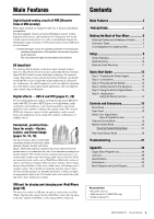
21 Rear Input/Output Block 25 Troubleshooting 27 Appendix 28 Digital Effect Program List 28 Jack List 29 Specifications 30 Dimensions 32 Block Diagram and Level Diagram 33 Accessories • AC power cord (1) • Rack mount kit (1) (MGP12X only) • Owner's manual (1) MGP16X/MGP12X Owner's Manual 3 - Yamaha MGP16X | Owner's Manual - Page 4
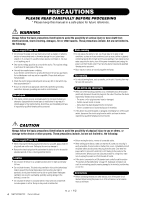
problems occur, immediately turn off the power switch and disconnect the electric plug from the outlet. Then have the device inspected by Yamaha service easily accessible. If some trouble or malfunction occurs, rack, carefully read the section "Precautions for Rack MGP12X Owner's Manual PA_en_1 1/2 - Yamaha MGP16X | Owner's Manual - Page 5
Yamaha service cause problems with manual are for instructional purposes only, and may appear somewhat different from those on your device. • Throughout this manual, all panel illustrations show the panel of the MGP16X. • In this manual the term "MGP" refers to both the MGP16X and MGP12X. In cases - Yamaha MGP16X | Owner's Manual - Page 6
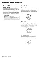
audio sources to the mixer's inputs, as well as to connect the mixer's outputs to a power jacks, and also to carry balanced signals in many cases. Unbalanced types are used for mono signals -guitar cables channel and red for right audio channel, for example. White Red 6 MGP16X/MGP12X Owner's Manual - Yamaha MGP16X | Owner's Manual - Page 7
Mixer Level Adjustment for Optimum Mix Mix channels all the way down without changing the way they sound in the mix. You'll hear the difference, however, in the way the mix mix mix. MGP channels. Start with the Featured Part You can start working on a mix mix around it. For example, if you're mixing mix - Yamaha MGP16X | Owner's Manual - Page 8
MGP12X) USB : iPod/iPhone signal CH15/16 : iPod/iPhone signal CH11/12 iPod/ iPhone Powered monitor speakers Computer/Audio interface Synthesizer Headphones Exciter Portable recorder Powered speakers Powered monitor speakers (For musician monitoring) 8 MGP16X/MGP12X Owner's Manual Effect - Yamaha MGP16X | Owner's Manual - Page 9
(voice) Setup (MGP16X) USB (MGP12X) USB : iPod/iPhone signal CH15/16 : iPod/iPhone signal CH11/12 DJ mixer iPod/ iPhone CD player Headphones Computer/Audio interface Instrument, Microphone CH8 (for MC) * MGP12X: CH4 Powered speakers Power amp Speakers MGP16X/MGP12X Owner's Manual 9 - Yamaha MGP16X | Owner's Manual - Page 10
w e q w Fasten them to the mixer in order (as shown): q center, w front, and e back. CAUTION Be sure to use the same screws that were removed in step 1. Using other screws can cause damage. MGP16X 3. Mount the unit into the rack, and fasten it into place. 10 MGP16X/MGP12X Owner's Manual 13U 11U - Yamaha MGP16X | Owner's Manual - Page 11
the mixer in order (as shown): q center, w front, and e back. Similarly fasten the other side as well. CAUTION Be sure to use the included screws with the MGP12X. Using other screws can cause damage. 5. Mount the unit into the rack, and fasten it into place. 13U 11U MGP16X/MGP12X Owner's Manual 11 - Yamaha MGP16X | Owner's Manual - Page 12
Quick Start Guide We'll begin this guide by connecting a pair of the devices in the following order: peripheral devices (instrument, microphone, iPod) MGP mixer power amps (or powered speakers). Reverse this order when turning the power off , your ears, or both. 12 MGP16X/MGP12X Owner's Manual - Yamaha MGP16X | Owner's Manual - Page 13
4. Use the channel FX1/FX2 knobs to adjust the effect depth for each channel. 5. Use the FX1/FX2 RTN fader to adjust the over- all effect depth. Note that 3 PFL switches 5 Channel faders 3 AFL switches 4,6 STEREO master fader FX1/FX2 RTN faders 3,5 ON buttons 2 MGP16X/MGP12X Owner's Manual 13 - Yamaha MGP16X | Owner's Manual - Page 14
Quick Start Guide Built-in digital effects Your mixes can be further refined by adding ambience effects such as reverb or delay. The MGP's internal effects can be used to add reverb or delay to individual channels in the same way as external effects processors. Reverb and Delay Time Small - Yamaha MGP16X | Owner's Manual - Page 15
Controls and Connectors Front Panel 4 6 8 7 1 235 9 * Throughout this manual, all panel illustrations show the panel of the MGP16X. On the MGP12X, there are four channels in the mono input section (see 1 below) and 12 channels in the channel I/O connectors section (see 10 on the next page). - Yamaha MGP16X | Owner's Manual - Page 16
Controls and Connectors Rear Panel 12 11 10 Rear Input/Output Block 10. Channel I/O connectors section page 25 11. Master I/O connectors section page 26 12. Power section page 26 16 MGP16X/MGP12X Owner's Manual - Yamaha MGP16X | Owner's Manual - Page 17
The master controls, specifically, the STEREO fader and GROUP faders, are the means used to adjust the level of all signals from all of the mixer's input channels. The level meter LED shows the level of the signal flowing to the STEREO bus. MGP16X/MGP12X Owner's Manual 17 - Yamaha MGP16X | Owner's Manual - Page 18
announcement on the microphone. For effective use of this switch, see Step 6 on page 14. The switch lights when it is turned on. NOTE You can adjust the attenuation of the Ducker function in the detailed setting mode (see column on page 21). !7 !7 !7 !8 !8 !8 18 MGP16X/MGP12X Owner's Manual - Yamaha MGP16X | Owner's Manual - Page 19
the channel into the FX bus. These knobs should generally be set close to the "t" position. NOTE • To send the signal to the bus engage the ON switch (!4). • On stereo channels, the LINE L (odd) and LINE R (even) input signals are mixed before moving into the bus. MGP16X/MGP12X Owner's Manual 19 - Yamaha MGP16X | Owner's Manual - Page 20
below. Switch TO CH15/16 (MGP16X) TO CH11/12 (MGP12X) Switch Setting ANALOG USB Audio Signal Input Source CH15/16 jacks (MGP16X) CH11/12 jacks (MGP12X) iPod/iPhone Output Destination Channels CH15/16 (MGP16X) Ch11/12 (MGP12X) TO 2TR IN ANALOG USB 2TR IN jacks iPod/iPhone 2TR IN NOTE • The - Yamaha MGP16X | Owner's Manual - Page 21
you've changed the parameter value from the default), a dot indication is displayed at the lower right of the FX2 program number. Built-in digital effects section q w e r t y u i o !0 MGP16X/MGP12X Owner's Manual 21 - Yamaha MGP16X | Owner's Manual - Page 22
status of the internal effects will be retained, even when you turn off the power. u SIG indicator Lights when an effect signal is input into the channel. i Bus assign page 28. • The mixer retains the last tempo setting made, even after the power is turned off. 22 MGP16X/MGP12X Owner's Manual - Yamaha MGP16X | Owner's Manual - Page 23
MONITOR OUT jacks. w POWER indicator This indicator lights up when the mixer's power is ON. e Level meter This LED meter displays the clipping level. NOTE The PFL signal has display priority when an input channel's PFL switch is on ( ). r MONITOR/PHONES control Controls the /MGP12X Owner's Manual 23 - Yamaha MGP16X | Owner's Manual - Page 24
jacks. NOTE These SEND MASTER controls do not affect the level of the signal sent from the internal digital effect to the FX1 and FX2 buses. w AFL switch and indicator When the AFL (After-Fader Listen) switch Adjusts the signal level sent to the STEREO OUT jacks. 24 MGP16X/MGP12X Owner's Manual - Yamaha MGP16X | Owner's Manual - Page 25
. This should not be a problem when connecting to an effect unit, but please be aware of the possibility of phase conflict when connecting to other types of device. A reversed-phased signal may result in degraded sound quality or even complete sound cancellation. MGP16X/MGP12X Owner's Manual 25 - Yamaha MGP16X | Owner's Manual - Page 26
external mixer, or another similar device. o SEND You use these jacks, for example, to connect to an effect device TRS phone type balanced output jacks that output the mixed stereo signal. The signal level is adjusted by the MGP, and then plug it into an AC outlet. 26 MGP16X/MGP12X Owner's Manual - Yamaha MGP16X | Owner's Manual - Page 27
? You might have to lower the COMP control levels. Is the GAIN control on the stereo channels adjusted appropriately? The Leveler may not be enabled if you increase the gain too much. * If any specific problem should persist, please contact your Yamaha dealer. MGP16X/MGP12X Owner's Manual 27 - Yamaha MGP16X | Owner's Manual - Page 28
5 SMALL STAGE 6 VOCAL ECHO 7 KARAOKE ECHO 8 DELAY 9 SINGLE DELAY 10 EARLY REF. 11 CHORUS 12 PHASER 13 FLANGER 14 SYMPHONIC 15 DOUBLER 16 . Phase modulation produces a cyclical phasing effect. Creates a tone with pitched effect. Creates a thick sound by multiplexing the /MGP12X Owner's Manual - Yamaha MGP16X | Owner's Manual - Page 29
Hot (+) Pin 3: Cold (-) * LINE (mono channels) GROUP OUT, STEREO OUT, MONITOR OUT, FX SEND channels) Tip: Hot Sleeve: Ground Sleeve Tip Phone Jack * These jacks will also accept connection to phone plugs. If you use monaural plugs, the connection will be unbalanced. MGP16X/MGP12X Owner's Manual - Yamaha MGP16X | Owner's Manual - Page 30
5.6" x 19.5") MGP16X: 9.0 kg (19.8 lb) MGP12X: 7.5 kg (16.5 lb) * The device may not function depending on your iPod/iOS software version. For updated information about supported software versions, check the Yamaha Pro Audio website (http://www.yamahaproaudio.com/). 30 MGP16X/MGP12X Owner's Manual - Yamaha MGP16X | Owner's Manual - Page 31
-80 dBu (0.078 mV) -60 dBu (0.775 mV) -40 dBu (7.75 mV) -36 dBu (12.3 mV) -16 dBu (123 mV) +4 dBu (1.23 V) Combo jack*2 -54 dBu (1.55 mV) ) Digital Input Specifications Connector USB IN Format iPod, iPhone exclusive Connector Specification USB A type MGP16X/MGP12X Owner's Manual 31 - Yamaha MGP16X | Owner's Manual - Page 32
Appendix Dimensions MGP16X 447 (444 excluding screw heads) 146 143 478 495 MGP12X 348 (345 excluding screw heads) 146 143 478 495 Unit: mm * Specifications and descriptions in this owner's manual are for information purposes only. Yamaha Corporation reserves the right to modify products or - Yamaha MGP16X | Owner's Manual - Page 33
/MGP12X Owner's Manual 33 CH INPUT MIC/LINE [-60dBu~-16dBu] [-34dBu~+10dBu] INSERT [0dBu] SOURCE CH INPUT ST CH INPUT MIC [-60dBu~-16dBu] L/MONO LINE [-34dBu~+10dBu] R ST CH INPUT - Yamaha MGP16X | Owner's Manual - Page 34
34 MGP16X/MGP12X Owner's Manual - Yamaha MGP16X | Owner's Manual - Page 35
instructions contained in this manual, meets FCC requirements. Modifications not expressly approved by Yamaha try to eliminate the problem by using one of line filter/s. In the case of radio or TV operation. CANADA This be mixed effects waste disposal service or the MGP12X Owner's Manual 35 - Yamaha MGP16X | Owner's Manual - Page 36
más cercana o el distribuidor autorizado que se lista debajo. NORTH AMERICA CANADA Yamaha Canada Music Ltd. 135 Milner Avenue, Scarborough, Ontario, M1S 3R1, Canada Tel: 416-298-1311 U.S.A. Yamaha Corporation of America 6600 Orangethorpe Ave., Buena Park, Calif. 90620, U.S.A. Tel: 714-522-9011
-
 1
1 -
 2
2 -
 3
3 -
 4
4 -
 5
5 -
 6
6 -
 7
7 -
8
-
9
-
10
-
11
-
12
-
13
-
14
-
15
-
16
-
17
-
18
-
19
-
20
-
21
-
22
-
23
-
24
-
25
-
26
-
27
-
28
-
29
-
30
-
31
-
32
-
33
-
34
-
35
-
36
 |
 |
EN
Owner’s Manual
Precautions
pages 4, 5
Quick Start Guide
pages 12 to 14
Troubleshooting
page 27