Yamaha MGP16X Owner's Manual - Page 25
Rear Input/Output Block, Channel I/O connectors
 |
View all Yamaha MGP16X manuals
Add to My Manuals
Save this manual to your list of manuals |
Page 25 highlights
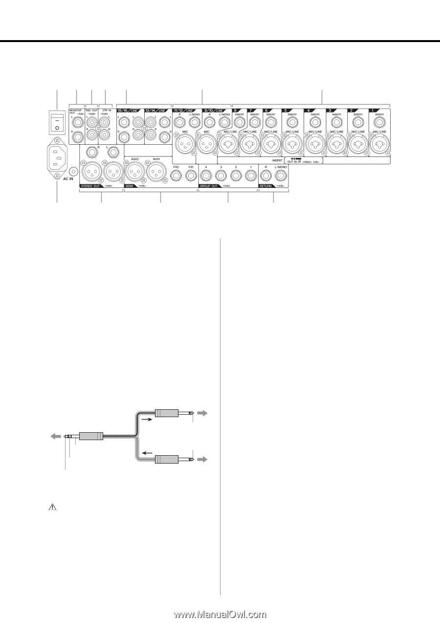
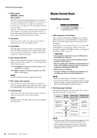
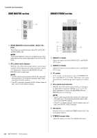
Rear Input/Output Block !1 y t r e (MGP12X: CHs 9/10, 11/12) w (MGP12X: CHs 5/6, 7/8) Controls and Connectors q (MGP12X: CHs 1 to 4) !2 !0 o i u Channel I/O connectors section q Mono inputs • INSERT: These jacks are located between the compressor and equalizer of the corresponding input channel. The INSERT jacks are ideal for connecting devices such as graphic equalizers or noise filters into the corresponding channels. These are TRS (tip, ring, sleeve) phone jacks that carry both the send and return signal (tip = send/out; ring = return/in; sleeve = ground). NOTE Connection to an INSERT I/O jack requires a special insertion cable as illustrated below. Use a separately-sold Yamaha insertion cable (YIC025/050/070). To the input jack of the external processor To the INSERT I/O jack Tip: OUT Sleeve (ground) Ring: IN Tip: OUT Tip: IN To the output jack of the external processor • MIC/LINE: These are combo jacks that support both XLR-type and TRS phone-type plugs, and are for connection of both microphones and/or instruments. w Mono/Stereo inputs • LINE: These are unbalanced phone-jack stereo line inputs. • MIC: These are balanced XLR-type microphone input jacks. (1: Ground; 2: Hot; 3: Cold) NOTE On any given channel, you may use either an XLR or phone jack, but not both. e Stereo input • LINE: These are stereo input jacks that connect linelevel instruments, such as a synthesizer. These are unbalanced input jacks. Two jack types are provided: phone type and RCA pin type. NOTE On any given channel, you may use either a phone or RCA jack, but not both. CAUTION The signal output from the INSERT jacks is reversephased. This should not be a problem when connecting to an effect unit, but please be aware of the possibility of phase conflict when connecting to other types of device. A reversed-phased signal may result in degraded sound quality or even complete sound cancellation. MGP16X/MGP12X Owner's Manual 25
-
 1
1 -
2
-
3
-
4
-
5
-
6
-
7
-
8
-
9
-
10
-
11
-
12
-
13
-
14
-
15
-
16
-
17
-
18
-
19
-
 20
20 -
 21
21 -
 22
22 -
 23
23 -
 24
24 -
 25
25 -
 26
26 -
 27
27 -
 28
28 -
 29
29 -
 30
30 -
31
-
32
-
33
-
34
-
35
-
36
 |
 |