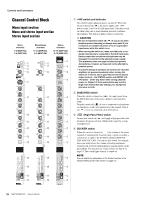
Yamaha MGP16X Owner's Manual - Page 23
Meter/PHONES RETURN/2TR IN PHONES jack, POWER indicator, Level meter
 |
View all Yamaha MGP16X manuals
Add to My Manuals
Save this manual to your list of manuals |
Page 23 highlights
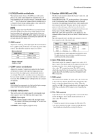
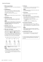
Meter/PHONES section q w Controls and Connectors RETURN/2TR IN section q w e r q PHONES jack Connect a pair of headphones to this TRS phone jack. The PHONES jack outputs the same signal as the MONITOR OUT jacks. w POWER indicator This indicator lights up when the mixer's power is ON. e Level meter This LED meter displays the level of the signal output from the STEREO OUT jack, or the signal selected by the 2TR IN switch and PFL/AFL switch. The "0" segment corresponds to the nominal output level. The PEAK segment lights when output reaches the clipping level. NOTE The PFL signal has display priority when an input channel's PFL switch is on ( ). r MONITOR/PHONES control Controls the level of the signal output to the PHONES jack and the MONITOR OUT jacks. q RETURN • AUX1, AUX2 controls: Adjust the level at which the L/ R signal received at the RETURN jacks (L (MONO) and R) is sent to the AUX1 and AUX2 buses. • STEREO control: Adjusts the level at which the signal received at the RETURN jacks (L (MONO) and R) is sent to the STEREO L/R bus. NOTE If you supply a signal to the RETURN L (MONO) jack only, the mixer sends the same signal to both the L and R Stereo buses. w 2TR IN • 2TR IN switch: If this switch is set to TO MONITOR ( ), the signals input via the 2TR IN jacks or the iPod/iPhone are sent to the MONITOR OUT jacks, the PHONES jack, and the level meter. If it is set to TO STEREO ( ), the signals are sent to the STEREO L/R buses. • 2TR IN control: Adjusts the level of the signal sent from the 2TR IN jacks or the iPod/iPhone to the STEREO L/R buses. MGP16X/MGP12X Owner's Manual 23
-
 1
1 -
2
-
3
-
4
-
5
-
6
-
7
-
8
-
9
-
10
-
11
-
12
-
13
-
14
-
15
-
16
-
17
-
 18
18 -
 19
19 -
 20
20 -
 21
21 -
 22
22 -
 23
23 -
 24
24 -
 25
25 -
 26
26 -
 27
27 -
 28
28 -
29
-
30
-
31
-
32
-
33
-
34
-
35
-
36
 |
 |
