Yamaha MW12CX Owners Manual - Page 20
Digital Effect, Rear Input/Output FOOT SWITCH Jack, PROGRAM Dial, PARAMETER Control
 |
View all Yamaha MW12CX manuals
Add to My Manuals
Save this manual to your list of manuals |
Page 20 highlights
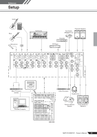
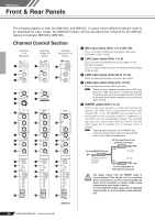
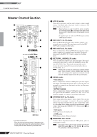
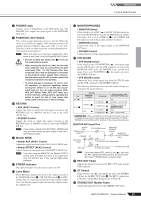
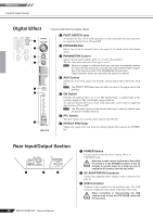
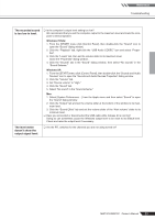
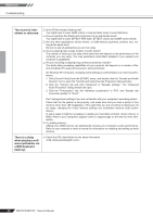
Reference Front & Rear Panels Digital Effect * Only the MW12CX has digital effects. 1 2 3 4 5 6 7 MW12CX 1 FOOT SWITCH Jack A Yamaha FC5 foot switch (sold separately) can be connected to this jack and used to toggle the digital effects ON and OFF. 2 PROGRAM Dial Selects one of the 16 internal effects. See page 21 for details about the internal effects. 3 PARAMETER Control Adjusts the parameter (depth, speed, etc.) for the selected effect. The last value used with each effect type is saved. NOTE When you change to a different effect type, the mixer automatically restores the value that was previously used with the newly selected effect (regardless of the current position of the PARAMETER Control knob). These parameter values are reset when the power is turned off. 4 AUX Control Adjusts the level of the signal sent from the internal digital effect unit to the AUX bus. NOTE The EFFECT RTN fader does not affect the level of the signal sent to the AUX bus. 5 ON Switch Switches the internal effect on or off. The internal effect is applied only if this switch is turned on. The switch lights orange when on. An optional Yamaha FC5 foot switch (sold separately) can be used to toggle the digital effects ON and OFF. NOTE The ON switch lights and the internal effect unit is active by default when the power is initially turned on. 6 PFL Switch Turn this switch on to send the effect signal to the PFL bus. 7 EFFECT RTN Fader Adjusts the signal level sent from the internal digital effect unit to the STEREO bus. Rear Input/Output Section 1 2 3 1 POWER Switch Use this switch to turn the mixer's power ON or to STANDBY mode. CAUTION Note that a small current continues to flow while the switch is in the STANDBY position. If you do not plan to use the mixer for a while, be sure to unplug the AC adaptor from the wall outlet. 2 AC ADAPTOR IN Connector Connect the supplied power adaptor to this connector (see page 6). 3 USB Connector Connects to the computer via the included cable. The USB connector outputs the same signal as the REC OUT jacks. When connecting or disconnecting the USB cable be sure to turn the 2TR IN/USB control all CAUTION the way down. 20 MW12CX/MW12C Owner's Manual
-
 1
1 -
2
-
3
-
4
-
5
-
6
-
7
-
8
-
9
-
10
-
11
-
12
-
13
-
14
-
 15
15 -
 16
16 -
 17
17 -
 18
18 -
 19
19 -
 20
20 -
 21
21 -
 22
22 -
 23
23 -
 24
24 -
 25
25 -
26
-
27
-
28
-
29
-
30
-
31
-
32
-
33
-
34
 |
 |
