Yamaha MW12CX Owners Manual - Page 25
Specifications, Electrical Specifications, General Specifications
 |
View all Yamaha MW12CX manuals
Add to My Manuals
Save this manual to your list of manuals |
Page 25 highlights
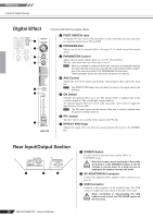
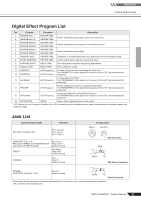
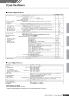
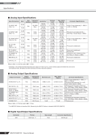
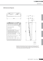
Reference Specifications ■ Electrical Specifications Frequency Response Total Harmonic Distortion (THD + N) Hum & Noise Hum & Noise are measured with a 6 dB/ octave filter @ 12.7 kHz; equivalent to a 20 kHz filter with infinite dB/octave attenuation. Crosstalk (1 kHz) Maximum voltage gain (1 kHz) All faders and controls are maximum when measured. PAN/BAL: panned hard left or hard right Phantom Voltage STEREO OUT GAIN: min (CHs 1-7/8) REC OUT2 20 Hz-20 kHz EFFECT/AUX (AUX1, 2*) SEND Nominal output level @1 kHz Input: CHs 1 to 11/12, RETURN, 2TR IN MONITOR OUT, REC OUT1 STEREO OUT +14 dBu @ 20 Hz-20 kHz, Input GAIN Control at minimum CH INPUT 1-4 MIC EIN (Equivalent Input Noise): Rs = 150 Ω, GAIN: maximum STEREO OUT STEREO OUT, REC OUT fader at nominal level and all chanREC OUT2 nels' ST and REC switches off. EFFECT/AUX Master EFFECT/AUX (AUX1, 2) control at nominal level and all (AUX1, 2*) SEND CH EFFECT/AUX (AUX1, 2) controls at minimum. STEREO OUT STEREO OUT, REC OUT fader and one CH fader at nominal REC OUT2 level. STEREO OUT Residual Output Noise Adjacent Input CHs 1-4 Input to Output STEREO L/R, CHs 1-4, PAN: panned hard left or right Rs = 150 Ω MIC to CH INSERT OUT INPUT GAIN: maximum MIC to STEREO OUT MIC to REC OUT2 MIC to REC to ST MIC to REC OUT1 MIC to MONITOR OUT, ST TO MONITOR MIC to PHONES OUT MIC to AUX (AUX1*) SEND PRE MIC to AUX (AUX1*) SEND POST, EFFECT (AUX2*) SEND CH 5/6, 7/8 LINE to STEREO OUT CH 5/6, 7/8 LINE to REC OUT2 CH 5/6, 7/8 AUX (AUX1*) SEND PRE CH 5/6, 7/8 LINE to AUX (AUX1*) SEND POST, EFFECT (AUX2*) SEND CH 9/10, 11/12 to STEREO OUT CH 9/10, 11/12 to REC OUT2 Rs = 150 Ω RETURN to STEREO OUT RETURN to EFFECT (AUX2*) SEND Rs = 600 Ω 2TR IN to STEREO OUT MIC no load MIN TYP MAX UNIT -3.0 0.0 1.0 dB 0.1 % -128 -88 -81 dBu -64 -98 -70 dB -70 60 84 94 72.2 84 83 76 86 dB 58 47 57 34 16 9 27.8 48 V ■ General Specifications USB Audio Input HPF Input equalization ±15 dB maximum Turn over/roll-off frequency of shelving: 3 dB blow maximum variable level. PEAK Indicator Internal Digital Effect (Only MW12CX) LED Level Meter Power Supply Adaptor Power Consumption Dimensions (W x H x D) Net Weight Input/Output: 44.1/48 kHz CHs 1-7/8, 80 Hz, 12 dB/oct CHs 1-7/8 HIGH: 10 kHz (shelving) MID: 2.5 kHz (peaking) LOW: 100 Hz (shelving) CH 9/10-11/12 HIGH: 10 kHz (shelving) LOW: 100 Hz (shelving) Red LED turns on when post EQ signal (either post MIC HA or post EQ signal for CHs 5/6, 7/8) reaches -3 dB below clipping (+17 dBu). 16 PROGRAM, PARAMETER control Foot Switch (Digital Effect On/Off) Pre MONITOR Level 2x12 points LED meter (PEAK, +10, +6, +3, 0, -3, -6, -10, -15, -20, -25, -30 dB) PEAK lights if the signal level reaches 3 dB below the clipping level. PA-20 AC 35 VCT, 0.94 A, Cable Length = 3.6 m 30 W 346.2 mm x 86.1 mm x 436.6 mm 3.2 kg (MW12CX), 3 kg (MW12C) All faders are nominal if not specified. Output impedance of signal generator: 150 ohms * The MW12CX feature is described first, followed by the MW12C feature in brackets: MW12CX (MW12C) MW12CX/MW12C Owner's Manual 91
-
 1
1 -
2
-
3
-
4
-
5
-
6
-
7
-
8
-
9
-
10
-
11
-
12
-
13
-
14
-
15
-
16
-
17
-
18
-
19
-
 20
20 -
 21
21 -
 22
22 -
 23
23 -
 24
24 -
 25
25 -
 26
26 -
 27
27 -
 28
28 -
 29
29 -
 30
30 -
31
-
32
-
33
-
34
 |
 |