Yamaha MW12CX Owners Manual - Page 21
Digital Effect Program List, Jack List
 |
View all Yamaha MW12CX manuals
Add to My Manuals
Save this manual to your list of manuals |
Page 21 highlights
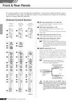
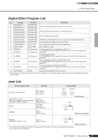
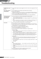
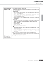
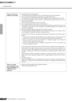
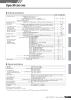
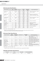
Reference Front & Rear Panels Digital Effect Program List No Program Parameter Description 1 REVERB HALL 1 2 REVERB HALL 2 REVERB TIME REVERB TIME Reverb simulating a large space such as a concert hall. 3 REVERB ROOM 1 REVERB TIME Reverb simulating the acoustics of a small space (room). 4 REVERB ROOM 2 REVERB TIME 5 REVERB STAGE 1 REVERB TIME Reverb simulating a large stage. 6 REVERB STAGE 2 REVERB TIME 7 REVERB PLATE REVERB TIME Simulation of a metal-plate reverb unit, producing a more hard-edged sound. 8 DRUM AMBIENCE REVERB TIME A short reverb that is ideal for use with kick drum. 9 KARAOKE ECHO DELAY TIME Echo designed for karaoke (sing-along) applications. 10 VOCAL ECHO DELAY TIME Echo suitable for vocals. 11 CHORUS 1 12 CHORUS 2 LFO Frequency LFO Frequency Creates a thick sound by modulating the delay time. The PARAMETER control adjusts the frequency of the LFO* that modulates the delay time. 13 FLANGER LFO Frequency A sweeping pitched effect. The PARAMETER control adjusts the frequency of the LFO* that modulates the delay time. 14 PHASER LFO Frequency Phase modulation produces a cyclical phasing effect. The PARAMETER control adjusts the frequency of the LFO* that modulates the delay time. 15 AUTO WAH LFO Frequency A wah-wah effect with cyclical filter modulation. The PARAMETER control adjusts the frequency of the LFO* that modulates the delay time. 16 DISTORTION DRIVE Adds a sharp-edged distortion to the sound. * "LFO" stands for Low Frequency Oscillator. An LFO is normally used to modulate another signal, determining the modulation speed and waveform shape. Jack List Input and Output Jacks Polarities MIC INPUT, STEREO OUT Pin 1: Ground Pin 2: Hot (+) Pin 3: Cold (-) LINE INPUT (CH1 to 4) REC OUT, STEREO OUT, MONITOR OUT, AUX (AUX1), EFFECT (AUX2)* INSERT Tip: Hot (+) Ring: Cold (-) Sleeve: Ground Tip: Output Ring: Input Sleeve: Ground PHONES Tip: L Ring: R Sleeve: Ground Configurations INPUT OUTPUT XLR Connector Ring Sleeve Tip TRS Phone Connector RETURN LINE INPUT (CH5/6 to 11/12) Tip: Hot Sleeve: Ground Sleeve Tip Phone Connector * These jacks will also accept connection to monaural phone Connectors. If you use monaural phone connectors, the connection will be unbalanced. MW12CX/MW12C Owner's Manual 21
-
 1
1 -
2
-
3
-
4
-
5
-
6
-
7
-
8
-
9
-
10
-
11
-
12
-
13
-
14
-
15
-
 16
16 -
 17
17 -
 18
18 -
 19
19 -
 20
20 -
 21
21 -
 22
22 -
 23
23 -
 24
24 -
 25
25 -
 26
26 -
27
-
28
-
29
-
30
-
31
-
32
-
33
-
34
 |
 |