Zenith Z52DC2D Operation Manual - Page 15
How to connect, How to use
 |
View all Zenith Z52DC2D manuals
Add to My Manuals
Save this manual to your list of manuals |
Page 15 highlights
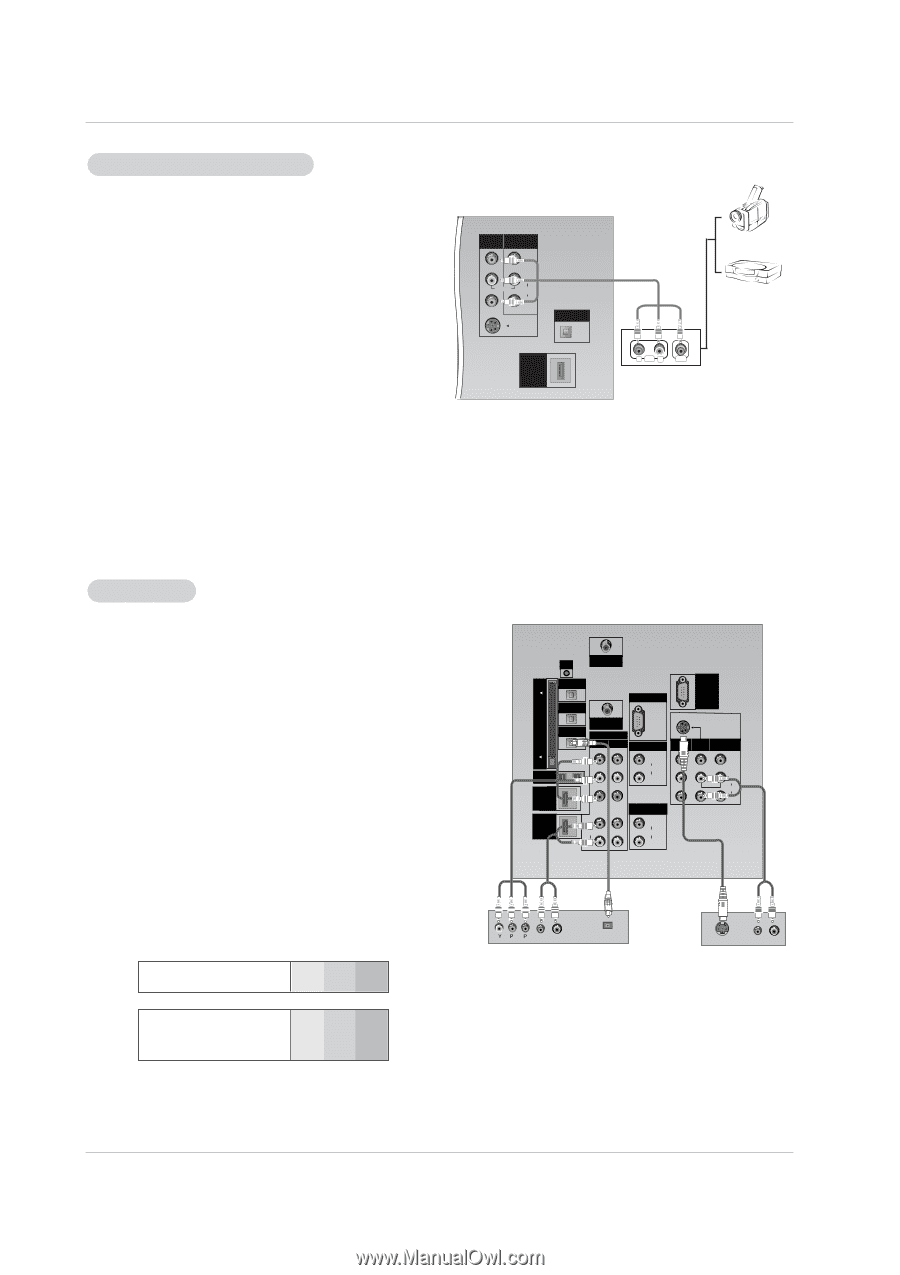
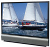
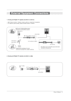
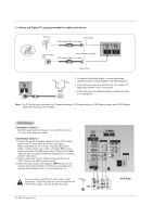
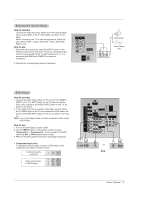
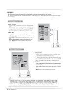
External A/V Source Setup How to connect Connect the audio and video cables from the external equipment's output jacks to the TV input jacks, as shown in the figure. When connecting the TV to external equipment, match the jack colors (Video = yellow, Audio Left = white, and Audio Right = red). How to use 1. Select the input source by using the INPUT button on the Remote Control. Note that this TV finds the connected input sources automatically for AV 1-2 and Component 1-2. It is presumed that RGB and HDMI/DVI sources are connected. 2. Operate the corresponding external equipment. AV IN 1 AV OUT VIDEO (L) MONO (R) (L) AUDIO (R) S-VIDEO DIGITAL AUDIO OPTICAL OUT HDMI /DVI IN Camcorder Video Game Set R AUDIO L VIDEO DVD Setup How to connect 1. Connect the DVD video outputs (Y, PB, PR) to the COMPO- NENT (Y, PB, PR) INPUT jacks on the TV and connect the DVD audio outputs to the AUDIO INPUT jacks on the TV, as shown in the figure. 2. If your DVD only has an S-Video output jack, connect this to the S-VIDEO input on the TV and connect the DVD audio outputs to the AUDIO INPUT jacks on the TV, as shown in the figure. Note: If your DVD player does not have component video output, use S-Video. How to use 1. Turn on the DVD player, insert a DVD. 2. Use the INPUT button on the remote control to select Component 1 or Component 2. (If connected to S-VIDEO, select the AV1 or AV2 external input source.) 3. Refer to the DVD player's manual for operating instructions. • Component Input ports To get better picture quality, connect a DVD player to the component input ports as shown below. Component ports on the TV Y PB PR Video output ports on DVD player Y Pb Pr Y B-Y R-Y Y Cb Cr Y PB PR G-LINK ANTENNA DIGITAL AUDIO OPTICAL OUT SERVICE RGB IN(PC/DTV) C DIGITAL AUDIO a OPTICAL IN 1 b (COMPONENT2) l e CABLE DIGITAL AUDIO C A OPTICAL IN 2 (DVI) COMPONENT IN XGA/ 480p/ 720p/ 1080i ONLY S-VIDEO R D 2 1 AUDIO IN(RGB/DVI) AV OUT AV IN 2 AV IN 1 Y IEEE-1394 IN PB HDMI IN 1 (DVI) PR (L) AUDIO (R) VARIABLE AUDIO OUT VIDEO (L) (MONO) AUDIO (R) HDMI IN 2 (L) AUDIO (R) (L) AUDIO (R) B R (R) AUDIO (L) DIGITAL AUDIO OPTICAL or DVD S-VIDEO (R) AUDIO (L) Owner's Manual 15
-
 1
1 -
2
-
3
-
4
-
5
-
6
-
7
-
8
-
9
-
 10
10 -
 11
11 -
 12
12 -
 13
13 -
 14
14 -
 15
15 -
 16
16 -
 17
17 -
 18
18 -
 19
19 -
 20
20 -
21
-
22
-
23
-
24
-
25
-
26
-
27
-
28
-
29
-
30
-
31
-
32
-
33
-
34
-
35
-
36
-
37
-
38
-
39
-
40
-
41
-
42
-
43
-
44
-
45
-
46
-
47
-
48
-
49
-
50
-
51
-
52
 |
 |