2004 Jeep Wrangler Owner's Manual - Page 255
2004 Jeep Wrangler Manual
Page 255 highlights
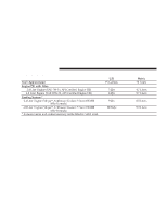
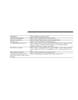
MAINTAINING YOUR VEHICLE 255 To access the fuse panel the glove box must be removed. It is removed by slipping the glove box strap off the hook and letting the door roll down off its hinges. To reinstall, position the glove box door at an 8 o'clock orientation, engage the hinge hook formations on the lower edge of the glove box door with the hinge pins on the lower edge of the instrument panel. Tilt the upper edge of the glove box door upward toward the instrument panel enough to reattach the glove box strap to the door. Rotate glove box door to closed position. Open and close to insure proper installation. Cavity Fuse Description 1 20 Amp Yellow Park Lights, Skim (Sentry Key) 2 20 Amp Yellow Stop Lights 3 20 Amp Yellow Subwoofer System 4 10 Amp Red Door Switch Defeat 5 10 Amp Red Airbag 6 20 Amp Yellow Rear Wiper 7 10 Amp Red Back-Up Lights, Rear Window Defroster Relay, ABS 8 10 Amp Red HEVAC Cavity 9 10 11 12 13 14 15 16 17 18 19 20 Fuse 10 Amp Red 10 Amp Red 10 Amp Red 10 Amp Red 10 Amp Red 10 Amp Red 10 Amp Red 10 Amp Red 25 Amp Natural 20 Amp Yellow Cigar Lighter 20 Amp Yellow Spare 20 Amp Yellow Transmission: Manual Clutch Interlock Switch Bypass Automatic - Ignition Starter Circuit Description Airbag Instrument Cluster Solenoids, DRL Power Distribution Relays, Skim (Sentry Key) Turn Signals Radio HBL (Rear Window Defroster) Switch Headlamp Aim (Export Only) Front Wiper 7
-
 1
1 -
2
-
3
-
4
-
5
-
6
-
7
-
8
-
9
-
10
-
11
-
12
-
13
-
14
-
15
-
16
-
17
-
18
-
19
-
20
-
21
-
22
-
23
-
24
-
25
-
26
-
27
-
28
-
29
-
30
-
31
-
32
-
33
-
34
-
35
-
36
-
37
-
38
-
39
-
40
-
41
-
42
-
43
-
44
-
45
-
46
-
47
-
48
-
49
-
50
-
51
-
52
-
53
-
54
-
55
-
56
-
57
-
58
-
59
-
60
-
61
-
62
-
63
-
64
-
65
-
66
-
67
-
68
-
69
-
70
-
71
-
72
-
73
-
74
-
75
-
76
-
77
-
78
-
79
-
80
-
81
-
82
-
83
-
84
-
85
-
86
-
87
-
88
-
89
-
90
-
91
-
92
-
93
-
94
-
95
-
96
-
97
-
98
-
99
-
100
-
101
-
102
-
103
-
104
-
105
-
106
-
107
-
108
-
109
-
110
-
111
-
112
-
113
-
114
-
115
-
116
-
117
-
118
-
119
-
120
-
121
-
122
-
123
-
124
-
125
-
126
-
127
-
128
-
129
-
130
-
131
-
132
-
133
-
134
-
135
-
136
-
137
-
138
-
139
-
140
-
141
-
142
-
143
-
144
-
145
-
146
-
147
-
148
-
149
-
150
-
151
-
152
-
153
-
154
-
155
-
156
-
157
-
158
-
159
-
160
-
161
-
162
-
163
-
164
-
165
-
166
-
167
-
168
-
169
-
170
-
171
-
172
-
173
-
174
-
175
-
176
-
177
-
178
-
179
-
180
-
181
-
182
-
183
-
184
-
185
-
186
-
187
-
188
-
189
-
190
-
191
-
192
-
193
-
194
-
195
-
196
-
197
-
198
-
199
-
200
-
201
-
202
-
203
-
204
-
205
-
206
-
207
-
208
-
209
-
210
-
211
-
212
-
213
-
214
-
215
-
216
-
217
-
218
-
219
-
220
-
221
-
222
-
223
-
224
-
225
-
226
-
227
-
228
-
229
-
230
-
231
-
232
-
233
-
234
-
235
-
236
-
237
-
238
-
239
-
240
-
241
-
242
-
243
-
244
-
245
-
246
-
247
-
248
-
249
-
 250
250 -
 251
251 -
 252
252 -
 253
253 -
 254
254 -
 255
255 -
 256
256 -
 257
257 -
 258
258 -
 259
259 -
 260
260 -
261
-
262
-
263
-
264
-
265
-
266
-
267
-
268
-
269
-
270
-
271
-
272
-
273
-
274
-
275
-
276
-
277
-
278
-
279
-
280
-
281
-
282
-
283
-
284
-
285
-
286
-
287
-
288
-
289
-
290
-
291
-
292
-
293
-
294
-
295
-
296
-
297
-
298
-
299
 |
 |
