3Com 3C81600 User Guide - Page 12
Advanced RPS Chassis — Front View Detail, LEDs, Bottom row left to right
 |
View all 3Com 3C81600 manuals
Add to My Manuals
Save this manual to your list of manuals |
Page 12 highlights
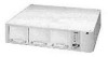
12 CHAPTER 1: INTRODUCING THE ADVANCED RPS Advanced RPS Chassis - Front View Detail Figure 1 Front View of the Advanced RPS Chassis LEDs The Advanced RPS chassis has LEDs visible on the front panel that indicate the status of the AC power inputs, the power modules, and the temperature of the chassis itself. One INPUT LED is allocated to each AC power input socket. Socket A is the right-hand one of the two sockets (labelled Primary Pwr A) when looking at the rear of the unit. Two OUTPUT LEDs, arranged vertically, are allocated to each power module slot on the rear of the Advanced RPS. The numbering of the slots, when looking at the rear of the unit, is: s Top row (left to right) - 7, 5, 3, 1 s Bottom row (left to right) - 8, 6, 4, 2 The OVERTEMP LED provides an indication of the chassis temperature status. Table 1 lists the LEDs visible on the front of the Advanced RPS chassis and their status according to color. For information on using the LEDs for troubleshooting, see Appendix D.
-
 1
1 -
2
-
3
-
4
-
5
-
6
-
 7
7 -
 8
8 -
 9
9 -
 10
10 -
 11
11 -
 12
12 -
 13
13 -
 14
14 -
 15
15 -
 16
16 -
 17
17 -
18
-
19
-
20
-
21
-
22
-
23
-
24
-
25
-
26
-
27
-
28
-
29
-
30
-
31
-
32
-
33
-
34
-
35
-
36
-
37
-
38
-
39
-
40
-
41
-
42
-
43
-
44
-
45
-
46
-
47
-
48
-
49
-
50
-
51
-
52
-
53
-
54
-
55
-
56
-
57
-
58
-
59
-
60
-
61
-
62
-
63
-
64
 |
 |
