3Com 3C81600 User Guide - Page 20
need to remove power from the chassis before you remove or insert, a power module
 |
View all 3Com 3C81600 manuals
Add to My Manuals
Save this manual to your list of manuals |
Page 20 highlights
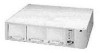
20 CHAPTER 1: INTRODUCING THE ADVANCED RPS Make sure you use the correct type of 'Y' cable for the right module combination. See "Power Modules" on page 15 for front views of the different connectors. If one of the power modules fails, the other module will take the full load. The faulty module can be "hot-swapped", that is, you do not need to remove power from the chassis before you remove or insert a power module, to return the system to full redundancy. This prevents the reset that occurs in the managed redundancy mode. Refer to the Advanced RPS Type 3 Power Module Installation Guide and Advanced RPS Type 3 'Y' Cable Installation Guide. Figure 10 Advanced RPS Full Redundancy Configuration
-
 1
1 -
2
-
3
-
4
-
5
-
6
-
7
-
8
-
9
-
10
-
11
-
12
-
13
-
14
-
 15
15 -
 16
16 -
 17
17 -
 18
18 -
 19
19 -
 20
20 -
 21
21 -
 22
22 -
 23
23 -
 24
24 -
 25
25 -
26
-
27
-
28
-
29
-
30
-
31
-
32
-
33
-
34
-
35
-
36
-
37
-
38
-
39
-
40
-
41
-
42
-
43
-
44
-
45
-
46
-
47
-
48
-
49
-
50
-
51
-
52
-
53
-
54
-
55
-
56
-
57
-
58
-
59
-
60
-
61
-
62
-
63
-
64
 |
 |

20
C
HAPTER
1: I
NTRODUCING
THE
A
DVANCED
RPS
Make sure you use the correct type of
’
Y
’
cable for the right module
combination. See
“
Power Modules
”
on page 15 for front views of
the different connectors.
If one of the power modules fails, the other module will take the full
load. The faulty module can be
“
hot-swapped
”
, that is, you do not
need to remove power from the chassis before you remove or insert
a power module, to return the system to full redundancy. This
prevents the reset that occurs in the managed redundancy mode.
Refer to the Advanced RPS Type 3 Power Module Installation Guide
and Advanced RPS Type 3
‘
Y
’
Cable Installation Guide.
Figure 10
Advanced RPS Full Redundancy Configuration