3Ware 8006-2LP User Guide - Page 18
RAID 5 arrays optimize performance, fault tolerance, high capacity and storage efficiency - 2 port
 |
UPC - 000060227379
View all 3Ware 8006-2LP manuals
Add to My Manuals
Save this manual to your list of manuals |
Page 18 highlights
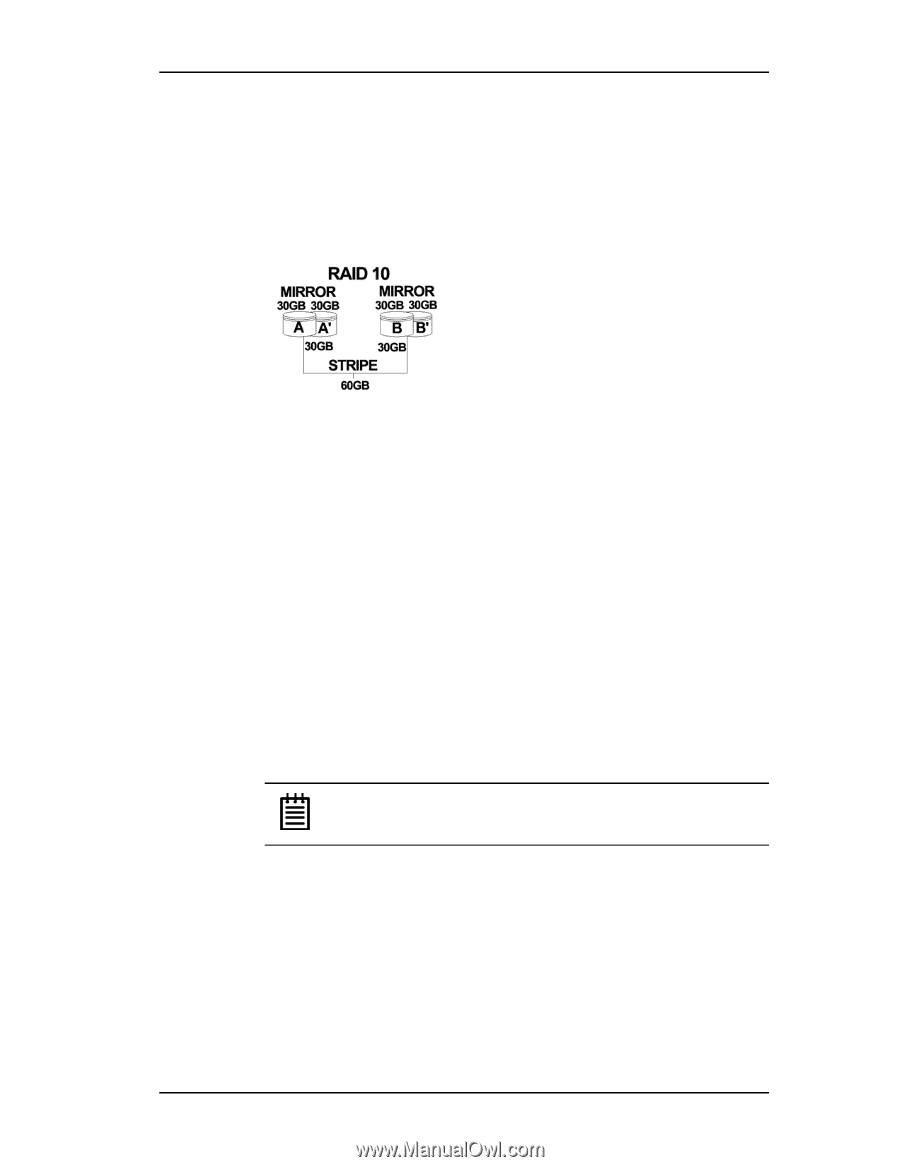
Introduction array using RAID 1. The two mirrored arrays are then grouped as a striped RAID 0 array using a two tier structure. Higher data transfer rates are achieved by leveraging TwinStor and striping (64K, 128K, 256K, 512K or 1M) the arrays. RAID 10 is available on the four, eight, and twelve port Escalade ATA RAID Controllers Figure 3. RAID 10 Configuration Example RAID 5 arrays optimize performance, fault tolerance, high capacity and storage efficiency The RAID 5 configuration features the data striping of RAID 0 combined with the parity of RAID 4. Using a simple parity (exclusive OR) function, RAID 5 can tolerate the loss of one drive. Parity information is distributed across all drives rather than being concentrated on a single disk (see Figure 4). This avoids throughput loss due to contention for the parity drive. You can use hot spares to rebuild a failed drive "on-the-fly". RAID 5 capacity = size of smallest drive × (number of drives - 1). In addition, the array's storage efficiency increases with the number of disks; from 66.7% for 3 drives to 87.5% for 8 drives: storage efficiency = (number of drives -1) ÷ (number of drives). Unlike all other RAID configurations that offer data striping, except for RAID 1, RAID 5 stripe size is limited to 64k. Note: BIOS will reject the creation of a RAID 5 array having less than 3 drives. 10 3ware Escalade ATA RAID Controller User Guide
-
 1
1 -
2
-
3
-
4
-
5
-
6
-
7
-
8
-
9
-
10
-
11
-
12
-
 13
13 -
 14
14 -
 15
15 -
 16
16 -
 17
17 -
 18
18 -
 19
19 -
 20
20 -
 21
21 -
 22
22 -
 23
23 -
24
-
25
-
26
-
27
-
28
-
29
-
30
-
31
-
32
-
33
-
34
-
35
-
36
-
37
-
38
-
39
-
40
-
41
-
42
-
43
-
44
-
45
-
46
-
47
-
48
-
49
-
50
-
51
-
52
-
53
-
54
-
55
-
56
-
57
-
58
-
59
-
60
-
61
-
62
-
63
-
64
-
65
-
66
-
67
-
68
-
69
-
70
-
71
-
72
-
73
-
74
-
75
-
76
-
77
-
78
-
79
-
80
-
81
-
82
-
83
-
84
-
85
-
86
-
87
-
88
-
89
-
90
-
91
-
92
-
93
-
94
-
95
-
96
-
97
-
98
-
99
-
100
-
101
-
102
-
103
-
104
-
105
-
106
-
107
-
108
-
109
-
110
-
111
-
112
-
113
-
114
-
115
-
116
-
117
-
118
-
119
-
120
-
121
-
122
-
123
-
124
-
125
-
126
 |
 |