AMD AXDA3200DKV4E Data Sheet - Page 7
List of s - processor
 |
View all AMD AXDA3200DKV4E manuals
Add to My Manuals
Save this manual to your list of manuals |
Page 7 highlights
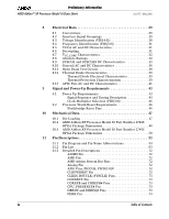
26237C-May 2003 Preliminary Information AMD Athlon™ XP Processor Model 10 Data Sheet List of Figures Figure 1. Typical AMD Athlon™ XP Processor Model 10 System Block Diagram 3 Figure 2. Logic Symbol Diagram 7 Figure 3. AMD Athlon XP Processor Model 10 Power Management States 9 Figure 4. AMD Athlon System Bus Disconnect Sequence in the Stop Grant State 14 Figure 5. Exiting the Stop Grant State and Bus Connect Sequence . . . . 15 Figure 6. Northbridge Connect State Diagram 16 Figure 7. Processor Connect State Diagram 17 Figure 8. SYSCLK Waveform 22 Figure 9. SYSCLK Waveform 26 Figure 10. VCC_CORE Voltage Waveform 33 Figure 11. SYSCLK and SYSCLK# Differential Clock Signals 35 Figure 12. General ATE Open-Drain Test Circuit 38 Figure 13. Signal Relationship Requirements During Power-Up Sequence 43 Figure 14. AMD Athlon XP Processor Model 10 Part Number 27488 OPGA Package Diagram 49 Figure 15. AMD Athlon XP Processor Model 10 Part Number 27493 OPGA Package Diagram 51 Figure 16. AMD Athlon XP Processor Model 10 Pin Diagram -Topside View 54 Figure 17. AMD Athlon XP Processor Model 10 Pin Diagram -Bottomside View 55 Figure 18. OPN Example for the AMD Athlon XP Processor Model 10 79 List of Figures vii
-
 1
1 -
 2
2 -
 3
3 -
 4
4 -
 5
5 -
 6
6 -
 7
7 -
 8
8 -
 9
9 -
 10
10 -
 11
11 -
 12
12 -
13
-
14
-
15
-
16
-
17
-
18
-
19
-
20
-
21
-
22
-
23
-
24
-
25
-
26
-
27
-
28
-
29
-
30
-
31
-
32
-
33
-
34
-
35
-
36
-
37
-
38
-
39
-
40
-
41
-
42
-
43
-
44
-
45
-
46
-
47
-
48
-
49
-
50
-
51
-
52
-
53
-
54
-
55
-
56
-
57
-
58
-
59
-
60
-
61
-
62
-
63
-
64
-
65
-
66
-
67
-
68
-
69
-
70
-
71
-
72
-
73
-
74
-
75
-
76
-
77
-
78
-
79
-
80
-
81
-
82
-
83
-
84
-
85
-
86
-
87
-
88
-
89
-
90
-
91
-
92
-
93
-
94
-
95
-
96
-
97
-
98
-
99
-
100
-
101
-
102
-
103
-
104
 |
 |
