ASRock H510TM-ITX User Manual
ASRock H510TM-ITX Manual
 |
View all ASRock H510TM-ITX manuals
Add to My Manuals
Save this manual to your list of manuals |
ASRock H510TM-ITX manual content summary:
- ASRock H510TM-ITX | User Manual - Page 1
- ASRock H510TM-ITX | User Manual - Page 2
Version 1.0 Published March 2022 This device complies with Part 15 of the FCC Rules. Operation is subject to the following two conditions: (1) this device may not cause harmful interference, and (2) this device must accept any interference received, including interference that may cause undesired - ASRock H510TM-ITX | User Manual - Page 3
AUSTRALIA ONLY Our goods come with guarantees that cannot be excluded under the Australian Consumer Law. You are entitled to a replacement or refund for a major failure and compensation for any other reasonably foreseeable loss or damage caused by our goods. You are also entitled to have the goods - ASRock H510TM-ITX | User Manual - Page 4
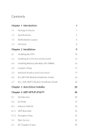
Memory Modules (SO-DIMM) 14 2.4 Jumpers Setup 15 2.5 Onboard Headers and Connectors 17 2.6 M.2 WiFi/BT Module Installation Guide 22 2.7 M.2_SSD (NGFF) Module Installation Guide 24 Chapter 3 Auto Driver Installer 29 Chapter 4 UEFI SETUP UTILITY 30 4.1 Introduction 30 4.2 EZ Mode 31 - ASRock H510TM-ITX | User Manual - Page 5
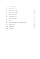
4.6 Advanced Screen 44 4.6.1 CPU Configuration 45 4.6.2 Chipset Configuration 47 4.6.3 Storage Configuration 50 4.6.4 ACPI Configuration 51 4.6.5 USB Configuration 52 4.6.6 Trusted Computing 53 4.7 Tools 55 4.8 Hardware Health Event Monitoring Screen 57 4.9 Security Screen 58 4. - ASRock H510TM-ITX | User Manual - Page 6
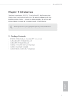
Chapter 1 and 2 contains the introduction of the motherboard and step-by-step installation guides. Chapter 3 contains the operation guide of the software and utilities. Chapter 4 contains the configuration guide of the BIOS setup. Because the motherboard specifications and the BIOS software might be - ASRock H510TM-ITX | User Manual - Page 7
ASRock's website for more information. (http://www.asrock.com/) • Max. capacity of system memory: 64GB • Supports Intel® Extreme Memory Profile (XMP) 2.0 Expansion Slot • 1 x M.2 Socket (Key E), supports type 2230 WiFi/BT module Graphics • Intel® UHD Graphics Built-in Visuals and the VGA outputs - ASRock H510TM-ITX | User Manual - Page 8
1 x Line out • 1 x MIC-In • PCIE x1 Gigabit LAN 10/100/1000 Mb/s • Realtek RTL8111H • Supports Wake-On-LAN • Supports Lightning/ESD Protection • Supports Energy Efficient Ethernet 802.3az • Supports PXE • 1 x DC Jack (Compatible with the 19V power adapter) • 1 x D-Sub Port * (Optional) 1 x COM Port - ASRock H510TM-ITX | User Manual - Page 9
• 1 x RJ-45 LAN Port with LED (ACT/LINK LED and SPEED LED) • HD Audio Jacks: Line out / Microphone Storage • 2 x SATA3 6.0 Gb/s Connectors, support NCQ, AHCI and Hot Plug • 1 x Ultra M.2 Socket, supports M Key type 2260/2280 M.2 SATA3 6.0 Gb/s module and M.2 PCI Express module up to Gen3 x4 (32 Gb - ASRock H510TM-ITX | User Manual - Page 10
H510TM-ITX OS Power Certifications • Microsoft® Windows® 10 64-bit / 11 64-bit • 1 x DC Jack (Supports 19V DC Power Adapters) • FCC, CE • ErP/EuP ready (ErP/EuP ready power supply is required) Please realize that there is a certain risk involved with - ASRock H510TM-ITX | User Manual - Page 11
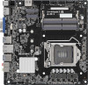
1.3 Motherboard Layout 1 2 3 45 6 7 8 9 10 11 HDMI1 VGA1 ATX_PWR1 DC Jack HDMI2 SATA_1 SATA_2 M.2 SSD CLR_MOS1 1 1 SATAPWR1 M.2 WiFi 1 SATAPWR2 1 USB2_1_2 USB2_3_4 RoHS 1 BLT_VOL1 PNL_PWR1 1 PANEL_SW1 1 1 BKT_PWR1 LVDS1 12 13 DDR4_A2 14 DDR4_A1 15 NUT1 CPU_FAN1 USB - ASRock H510TM-ITX | User Manual - Page 12
No. Description 1 4 pin 19V Power Connector (ATX_PWR1) 2 SATA Power Connector (SATAPWR2) 3 SATA3 Connector (SATA_1) 4 SATA Power Connector (SATAPWR1) 5 Clear CMOS Jumper (CLRCMOS1) 6 SATA3 Connector (SATA_2) 7 USB 2.0 Header (USB2_1_2) 8 USB 2.0 Header (USB2_3_4) 9 FPD Brightness Header (BLT_VOL1) - ASRock H510TM-ITX | User Manual - Page 13
FA130PE1-00-130W/19.5V LA90PE0-01-90W/19.5V DELTA-ADP-180TB-180W/19V FSP-FSP180-ABBN3-180W/19V This motherboard is available with support for either 4-pin ATX 19V power or DC-in power supplies. Please do not use two kinds of power supplies at the same time! Doing - ASRock H510TM-ITX | User Manual - Page 14
H510TM-ITX Chapter 2 Installation This is a Thin Mini-ITX form factor motherboard. Before you install the motherboard, study the configuration of your chassis to ensure that the motherboard fits into it. Pre-installation Precautions Take note of the following precautions before you install - ASRock H510TM-ITX | User Manual - Page 15
2.1 Installing the CPU 1. Before you insert the 1200-Pin CPU into the socket, please check if the PnP cap is on the socket, if the CPU surface is unclean, or if there are any bent pins in the socket. Do not force to insert the CPU into the socket if above situation is found. Otherwise, the CPU will - ASRock H510TM-ITX | User Manual - Page 16
H510TM-ITX 3 4 5 11 English - ASRock H510TM-ITX | User Manual - Page 17
Please save and replace the cover if the processor is removed. The cover must be placed if you wish to return the motherboard for after service. 12 English - ASRock H510TM-ITX | User Manual - Page 18
2.2 Installing the CPU Fan and Heatsink H510TM-ITX 1 2 CPU_FAN 13 English - ASRock H510TM-ITX | User Manual - Page 19
2.3 Installing Memory Modules (SO-DIMM) This motherboard provides two 260-pin DDR4 (Double Data Rate 4) SO-DIMM slots. It is not allowed to install a DDR, DDR2 or DDR3 memory module into a DDR4 slot; otherwise, this motherboard and SO-DIMM may be damaged. The SO-DIMM only fits in one correct - ASRock H510TM-ITX | User Manual - Page 20
H510TM-ITX 2.4 Jumpers Setup The illustration shows how jumpers are setup. When the jumper cap is placed on the pins, the jumper is "Short". If no jumper cap is placed on the pins, the jumper is "Open". Clear CMOS Jumper (CLRCMOS1) (see p.6, No. 5) 2-pin Jumper CLRMOS1 allows you to clear the - ASRock H510TM-ITX | User Manual - Page 21
Backlight Inverter Voltage Selection Header (3-pin BKT_PWR1) (see p.6, No. 11) 1-2 : +19V 2-3 : +12V Panel Voltage Selection Header (3-pin PNL_PWR1) (see p.6, No. 10) 1-2 : +3V 2-3 : +5V Warning: If selected Backlight Power or Panel Power is higher than panel's spec, it may damage the panel. - ASRock H510TM-ITX | User Manual - Page 22
H510TM-ITX 2.5 Onboard Headers and Connectors Onboard headers and connectors are NOT jumpers. Do NOT place jumper caps over these headers and connectors. Placing jumper caps over the headers and connectors will cause permanent damage to the motherboard. System Panel Header (9-pin PANEL1) (see p.6, - ASRock H510TM-ITX | User Manual - Page 23
(9-pin USB2_3_4) (see p.6, No. 8) USB_PWR PP+ GND DUMMY 1 GND P+ PUSB_PWR There are two headers on this motherboard. Each USB 2.0 header can support two ports. Front Panel Audio Header OUT_RET (9-pin HD_AUDIO1) (see p.6, No. 20) MIC_RED PRESENCE# GND OUT2_L This header is for J_SENSE OUT2_R - ASRock H510TM-ITX | User Manual - Page 24
Jack Sensing, but the panel wire on the chassis must support HDA to function correctly. Please follow the instructions in our manual and chassis manual to install your system. 2. If you use an AC'97 audio panel, please install it to the front panel audio header by the steps below: A. - ASRock H510TM-ITX | User Manual - Page 25
Thermal Sensor Header 1 (2-pin TH1) (see p.6, No. 21) Panel Off Header (2-pin PANEL_SW1) (see p.6, No. 12) 1 PWRDN GND This motherboard supports CASE OPEN detection feature that detects if the chassis cove has been removed. This feature requires a chassis with chassis intrusion detection - ASRock H510TM-ITX | User Manual - Page 26
Digital MIC Header 1 (5-pin DMIC1) (see p.6, No. 17) H510TM-ITX 1: +5V 2: No pin 3: DMIC_ CLK 4: GND 5: DMIC_DATA 6: +3.3V English 21 - ASRock H510TM-ITX | User Manual - Page 27
2.6 M.2 WiFi/BT Module Installation Guide The M.2, also known as the Next Generation Form Factor (NGFF), is a small size and versatile card edge connector that aims to replace mPCIe and mSATA. The M.2 Socket (Key E) supports type 2230 WiFi/BT module. Installing the WiFi/BT module Step 1 Prepare a - ASRock H510TM-ITX | User Manual - Page 28
H510TM-ITX Step 4 Tighten the screw with a screwdriver to secure the module into place. Please do not overtighten the screw as this might damage the module. A 23 English - ASRock H510TM-ITX | User Manual - Page 29
2.7 M.2_SSD (NGFF) Module Installation Guide The M.2, also known as the Next Generation Form Factor (NGFF), is a small size and versatile card edge connector that aims to replace mPCIe and mSATA. The Ultra M.2 Socket supports M Key type 2260/2280 M.2 SATA3 6.0 Gb/s module and M.2 PCI Express module - ASRock H510TM-ITX | User Manual - Page 30
B A B A B A H510TM-ITX Step 4 Move the standoff based on the module type and length. The standoff is placed at the nut location A by default. Skip Step 4 and 5 and go straight to Step 6 if you are going to use the default nut. Otherwise, release the standoff by hand. Step 5 Peel off the yellow - ASRock H510TM-ITX | User Manual - Page 31
M.2_SSD (NGFF) Module Support List M2_SATA: Vendor ADATA Crucial Crucial ezlink LITEON SanDisk SanDisk Transcend Transcend PLEXTOR INTEL INTEL V-ColorWD WD WD Capacity 512GB 240GB 250GB 120GB 256GB 128GB - ASRock H510TM-ITX | User Manual - Page 32
H510TM-ITX Vendor Samsung Samsung Samsung Samsung Team TOSHIBA TOSHIBA WD WD WD Capacity 128GB 512GB 250GB 250GB 240GB 256GB 128GB 512GB 1TB 512GB P/N Samsung MZ-VLW1280-128GB (PM961) Samsung MZ-V7P512-512G (970PRO) Samsung MZ-V7E250-250G (970EVO) Samsung MZ-V6E250-250G (960 EVO) Team CARDEA-240G - ASRock H510TM-ITX | User Manual - Page 33
Vendor INTEL SANDISK SANDISK PLEXTOR PLEXTOR CRUCIAL CRUCIAL OCZ OCZ WD WD UMAX PIONEER ANACONDA KLEVV TCELL Liteon V-Color HIKVISION SAMSUNG TEAM Capacity 128GB 128GB 240GB 256GB 256GB 250GB 120GB 120GB 120GB 120GB 250GB 240GB 120GB 240GB 240GB 240GB 240GB 240GB 480GB 250GB 250GB P/N 545S SERIES- - ASRock H510TM-ITX | User Manual - Page 34
H510TM-ITX Chapter 3 Auto Driver Installer After you install the Windows OS and boot into the system, a notification will pop up to help you to install and update required drivers. 29 English - ASRock H510TM-ITX | User Manual - Page 35
Chapter 4 UEFI SETUP UTILITY 4.1 Introduction This section explains how to use the UEFI SETUP UTILITY to configure your system. You may run the UEFI SETUP UTILITY by pressing or right after you power on the computer, otherwise, the Power-On-Self-Test (POST) will continue with its test - ASRock H510TM-ITX | User Manual - Page 36
H510TM-ITX 4.2 EZ Mode The EZ Mode screen appears when you enter the BIOS setup program by default. EZ mode is a dashboard which contains multiple readings of the system's current status. You can check the most crucial information of your system, such as CPU speed, DRAM frequency, SATA information, - ASRock H510TM-ITX | User Manual - Page 37
4.3 Advanced Mode The Advanced Mode provides more options to configure the BIOS settings. Refer to the following sections for the detailed configurations. To access the EZ Mode, press or click the "EZ Mode" button at the upper right corner of the screen. 4.3.1 UEFI Menu Bar The top of the - ASRock H510TM-ITX | User Manual - Page 38
H510TM-ITX 4.3.2 Navigation Keys Use < > key or < > key to choose among the selections on the menu bar, and use < > key or < > key to move the cursor up or down to select items, then press to get into the sub screen. You can also use the mouse to click your required item. Please check the - ASRock H510TM-ITX | User Manual - Page 39
4.4 Main Screen When you enter the UEFI SETUP UTILITY, the Main screen will appear and display the system overview. The availability and location of BIOS settings can be different for different models and BIOS versions. My Favorite Display your collection of BIOS items. Press F5 to add/remove your - ASRock H510TM-ITX | User Manual - Page 40
4.5 OC Tweaker Screen In the OC Tweaker screen, you can set up overclocking features. H510TM-ITX Because the UEFI software is constantly being updated, the following UEFI setup screens and descriptions are for reference purpose only, and they may not exactly match what you see on your screen. Base - ASRock H510TM-ITX | User Manual - Page 41
run above its base operating frequency when the operating system requests the highest performance state. Intel Speed Shift Technology Enable/Disable Intel Speed Shift Technology support. Enabling will expose the CPPC v2 interface to allow for hardware controlled P-sates. 36 English - ASRock H510TM-ITX | User Manual - Page 42
Intel Thermal Velocity Boost Voltage Optimizations This service controls thermal based voltage optimizations for processors that applicable for CMLS 35W/65W/125W skus. This item is only supported with processors with Config TDP support. Long Duration Power Limit Configure Package Power Limit 1 in - ASRock H510TM-ITX | User Manual - Page 43
DRAM Configuration Memory Information Allows users to browse the serial presence detect (SPD) and Intel extreme memory profile (XMP) for DDR4 modules. DRAM Timing Configuration Load XMP Setting Load XMP settings to overclock the memory and perform beyond standard specifications. DRAM Reference Clock - ASRock H510TM-ITX | User Manual - Page 44
H510TM-ITX Secondary Timing Write Recovery Time (tWR) The amount of delay that must elapse after the completion of a valid write operation, before an active bank can be precharged. Refresh Cycle Time (tRFC) The number of clocks from a Refresh command until the first Activate command to the same rank - ASRock H510TM-ITX | User Manual - Page 45
tCKE Configure the period of time the DDR4 initiates a minimum of one refresh command internally once it enters Self-Refresh mode. Turn Around Timing Turn Around Timing Optimization Auto is enabled in general case. tRDRD_sg Configure between module read to read delay. tRDRD_dg Configure between - ASRock H510TM-ITX | User Manual - Page 46
tWRRD_dr Configure between module write to read delay. tWRRD_dd Configure between module write to read delay. tWRWR_sg Configure between module write to write delay. tWRWR_dg Configure between module write to write delay. tWRWR_dr Configure between module write to write delay. tWRWR_dd Configure - ASRock H510TM-ITX | User Manual - Page 47
termination resistors' WR for channel B1. ODT NOM (A1) Use this to change ODT (CH A1) Auto/Manual settings. The default is [Auto]. ODT NOM (B1) Use this to change ODT (CH B1) Auto/Manual settings. The default is [Auto]. ODT PARK (A1) Configure the memory on die termination resistors' PARK for - ASRock H510TM-ITX | User Manual - Page 48
H510TM-ITX Realtime Memory Timing Configure the realtime memory timings. [Enabled] The system will allow performing realtime memory timing changes after MRC_DONE. Reset for MRC Failed Reset system after MRC training is failed. Train on Warm Boot When enabled, memory training will be executed when - ASRock H510TM-ITX | User Manual - Page 49
UEFI setup utility. Full HD UEFI When [Auto] is selected, the resolution will be set to 1920 x 1080 if the monitor supports Full HD resolution. If the monitor does not support Full HD resolution, then the resolution will be set to 1024 x 768. When [Disable] is selected, the resolution will be set - ASRock H510TM-ITX | User Manual - Page 50
on threaded software is improved. Active Processor Cores Select the number of cores to enable in each processor package. CPU C States Support Enable CPU C States Support for power saving. It is recommended to keep C6 and C7 all enabled for better power saving. Enhanced Halt State (C1E) Enable - ASRock H510TM-ITX | User Manual - Page 51
. This is applicable for Big Core only. Intel AVX-512 Enable/Disable the Intel AVX-512 (a.k.a. AVX3) Instructions. This is applicable for Big Core only. Intel Virtualization Technology Intel Virtualization Technology allows a platform to run multiple operating systems and applications in independent - ASRock H510TM-ITX | User Manual - Page 52
H510TM-ITX Above 4G Decoding Enable or disable 64bit capable Devices to be decoded in Above 4G Address Space (only if the system supports 64 bit PCI decoding). VT-d Intel® Virtualization Technology for Directed I/O helps your virtual machine monitor better utilize hardware by improving application - ASRock H510TM-ITX | User Manual - Page 53
This option enables/disables the control of ASPM on CPU side of the DMI Link. PCH DMI ASPM Support This option enables/disables the ASPM support for all PCH DMI devices. Share Memory Configure the size of memory that is allocated to the integrated graphics processor when the system boots up. - ASRock H510TM-ITX | User Manual - Page 54
Panel Type Selection Use this to select panel type. ME Update Enable/disable the Intel® ME Update. H510TM-ITX English 49 - ASRock H510TM-ITX | User Manual - Page 55
Link Power Management allows SATA devices to enter a low power state during periods of inactivity to save power. It is only supported by AHCI mode. Hard Disk S.M.A.R.T. S.M.A.R.T stands for Self-Monitoring, Analysis, and Reporting Technology. It is a monitoring system for computer hard disk - ASRock H510TM-ITX | User Manual - Page 56
4.6.4 ACPI Configuration H510TM-ITX Suspend to RAM Select disable for ACPI suspend type S1. It is recommended to select auto for ACPI S3 power saving. PCIE Devices Power On Allow the system to be waked up by a PCIE device and enable wake on LAN. RTC Alarm Power On Allow the system to be waked up - ASRock H510TM-ITX | User Manual - Page 57
4.6.5 USB Configuration XHCI Hand-off This is a workaround for OSes without XHCI hand-off support. The XHCI ownership change should be claimed by XHCI driver. 52 English - ASRock H510TM-ITX | User Manual - Page 58
4.6.6 Trusted Computing H510TM-ITX NOTE: Options vary depending on the version of your connected TPM module. Security Device Support Use this item to enable or disable BIOS support for security device. O.S. will not show Security Device. TCG EFI protocol and INT1A interface will not be available. - ASRock H510TM-ITX | User Manual - Page 59
Use this item to enable or disable Endorsement Hierarchy. TPM2.0 UEFI Spec Version Use this item to select the TCG2 spec. version supported. The optional settings: [TCG_1_2]; [TCG_2]. [TCG_1_2]: compatible mode for Win8/Win10. [TCG_2]: for TCG2 newer spec. compatible mode for Win10 Physical Presence - ASRock H510TM-ITX | User Manual - Page 60
4.7 Tools H510TM-ITX UEFI Tech Service Contact ASRock Tech Service if you are having trouble with your PC. Please setup network configuration before using UEFI Tech Service. SSD Secure Erase Tool All the SSD's listed that supports Secure Erase function. NVME Sanitization Tool After you Sanitize - ASRock H510TM-ITX | User Manual - Page 61
Network Configuration Use this to configure internet connection settings for Internet Flash. Internet Setting Enable or disable sound effects in the setup utility. UEFI Download Server Select a server to download the UEFI firmware. 56 English - ASRock H510TM-ITX | User Manual - Page 62
H510TM-ITX 4.8 Hardware Health Event Monitoring Screen This section allows you to monitor the status of the hardware on your system, including the parameters of the CPU temperature, motherboard temperature, fan speed and voltage. Fan Tuning Measure Fan Min Duty Cycle. Fan-Tastic Tuning Select a fan - ASRock H510TM-ITX | User Manual - Page 63
settings in the UEFI Setup Utility. Leave it blank and press enter to remove the password. Secure Boot Use this item to enable or disable support for Secure Boot. Intel(R) Platform Trust Technology Enable/disable Intel PTT in ME. Disable this option to use discrete TPM Module. 58 English - ASRock H510TM-ITX | User Manual - Page 64
priority. Fast Boot Fast Boot minimizes your computer's boot time. In fast mode you may not boot from an USB storage device. The VBIOS must support UEFI GOP if you are using an external graphics card. Please notice that Ultra Fast mode will boot so fast that the only way to - ASRock H510TM-ITX | User Manual - Page 65
Full Screen Logo Enable to display the boot logo or disable to show normal POST messages. AddOn ROM Display Enable AddOn ROM Display to see the AddOn ROM messages or configure the AddOn ROM if you've enabled Full Screen Logo. Disable for faster boot speed. Boot Failure Guard Message If the computer - ASRock H510TM-ITX | User Manual - Page 66
4.11 Exit Screen H510TM-ITX Save Changes and Exit When you select this option the following message, "Save configuration changes and exit setup?" will pop out. Select [OK] to save changes and exit the UEFI SETUP UTILITY. Discard Changes and Exit When you select this option the following message, " - ASRock H510TM-ITX | User Manual - Page 67
DECLARATION OF CONFORMITY Per FCC Part 2 Section 2.1077(a) Responsible Party Name: ASRock Incorporation Address: 13848 Magnolia Ave, Chino, CA91710 Phone/Fax No: +1-909-590-8308/+1-909-590-1026 hereby declares that the product Product Name : Motherboard Model Number : H510TM-ITX Conforms to the - ASRock H510TM-ITX | User Manual - Page 68
EU Declaration of Conformity For the following equipment: Motherboard (Product Name) H510TM-ITX (Model Designation / Trade Name) EMC Directive - 2014/30/EU EN 55032: 2015 / A11: 2020, EN 55035: 2017 / A11: 2020 EN IEC 61000-3-2: 2019, EN 61000-3-3: 2013 RoHS Directive - 2011/65/EU 2015/863/EU, EN - ASRock H510TM-ITX | User Manual - Page 69
EU Declaration of Conformity Product: Product Model Motherboard H510TM-ITX Authorized Representative (UK-GB): Name: Address: Contact person: Gary Tsui Bijsterhuizen 11-11, 6546 AR Nijmegen,The Netherlands Gary Tsui This declaration is issued under the sole responsibility of the mentioned
-
 1
1 -
 2
2 -
 3
3 -
 4
4 -
 5
5 -
 6
6 -
 7
7 -
8
-
9
-
10
-
11
-
12
-
13
-
14
-
15
-
16
-
17
-
18
-
19
-
20
-
21
-
22
-
23
-
24
-
25
-
26
-
27
-
28
-
29
-
30
-
31
-
32
-
33
-
34
-
35
-
36
-
37
-
38
-
39
-
40
-
41
-
42
-
43
-
44
-
45
-
46
-
47
-
48
-
49
-
50
-
51
-
52
-
53
-
54
-
55
-
56
-
57
-
58
-
59
-
60
-
61
-
62
-
63
-
64
-
65
-
66
-
67
-
68
-
69
 |
 |
