ASRock H510TM-ITX User Manual - Page 25
Signal Name
 |
View all ASRock H510TM-ITX manuals
Add to My Manuals
Save this manual to your list of manuals |
Page 25 highlights
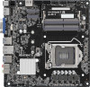
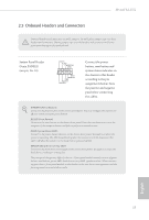
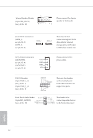
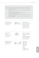
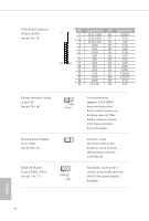
LVDS Panel Connector (30-pin LVDS1) (see p.6, No. 13) 12 29 30 PIN Signal Name PIN Signal Name 1 LCD_VDD 16 2 LCD_VDD 17 3 LCD_VDD 18 4 GND 19 5 N/A 20 6 GND 21 7 A0N 22 8 A0P 23 9 A1N 24 10 A1P 25 11 A2N 26 12 A2P 27 13 GND 28 14 GND 29 15 CLK1N 30 CLK1P A3N A3P A4N A4P A5N A5P A6N A6P GND GND CLK2N CLK2P A7N A7P Chassis Intrusion Header (2-pin CI1) (see p.6, No. 16) 1 GND Signal Thermal Sensor Header 1 (2-pin TH1) (see p.6, No. 21) Panel Off Header (2-pin PANEL_SW1) (see p.6, No. 12) 1 PWRDN GND This motherboard supports CASE OPEN detection feature that detects if the chassis cove has been removed. This feature requires a chassis with chassis intrusion detection design. Connect a 2-pin thermistor cable to this header to use an external thermal sensor with the motherboard. This header can be used to connect a switch that turns on/ off the LVDS panel display's backlight. English 20
-
 1
1 -
2
-
3
-
4
-
5
-
6
-
7
-
8
-
9
-
10
-
11
-
12
-
13
-
14
-
15
-
16
-
17
-
18
-
19
-
 20
20 -
 21
21 -
 22
22 -
 23
23 -
 24
24 -
 25
25 -
 26
26 -
 27
27 -
 28
28 -
 29
29 -
 30
30 -
31
-
32
-
33
-
34
-
35
-
36
-
37
-
38
-
39
-
40
-
41
-
42
-
43
-
44
-
45
-
46
-
47
-
48
-
49
-
50
-
51
-
52
-
53
-
54
-
55
-
56
-
57
-
58
-
59
-
60
-
61
-
62
-
63
-
64
-
65
-
66
-
67
-
68
-
69
 |
 |
