ASRock H510TM-ITX User Manual - Page 24
ATX 19V Power
 |
View all ASRock H510TM-ITX manuals
Add to My Manuals
Save this manual to your list of manuals |
Page 24 highlights
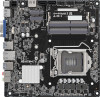
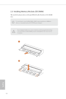
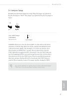
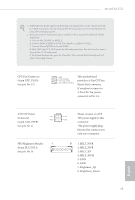
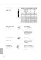
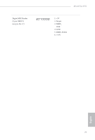
H510TM-ITX 1. High Definition Audio supports Jack Sensing, but the panel wire on the chassis must support HDA to function correctly. Please follow the instructions in our manual and chassis manual to install your system. 2. If you use an AC'97 audio panel, please install it to the front panel audio header by the steps below: A. Connect Mic_IN (MIC) to MIC2_L. B. Connect Audio_R (RIN) to OUT2_R and Audio_L (LIN) to OUT2_L. C. Connect Ground (GND) to Ground (GND). D. MIC_RET and OUT_RET are for the HD audio panel only. You don't need to connect them for the AC'97 audio panel. E. To activate the front mic, go to the "FrontMic" Tab in the Realtek Control panel and adjust "Recording Volume". CPU Fan Connector (4-pin CPU_FAN1) (see p.6, No. 15) 1 GND This motherboard 2 FAN_VOLTAGE 3 CPU_FAN_SPEED provides a 4-Pin CPU fan 4 FAN_SPEED_CONTROL (Quiet Fan) connector. If you plan to connect a 3-Pin CPU fan, please connect it to Pin 1-3. ATX 19V Power Connector +19V GND (4-pin ATX_PWR1 (see p.6, No. 1) FPD Brightness Header 1 (8-pin BLT_VOL1) (see p.6, No. 9) Please connect an ATX +19V 19V power supply to this GND connector. *The power supply plug fits into this connector in only one orientation. 8 1: BKLT_PWR 2: BKLT_PWR 3: BKLT_EN 4: BKLT_PWM 5: GND 6: GND 7: Brightness_Up 8: Brightness_Down 19 English
-
 1
1 -
2
-
3
-
4
-
5
-
6
-
7
-
8
-
9
-
10
-
11
-
12
-
13
-
14
-
15
-
16
-
17
-
18
-
 19
19 -
 20
20 -
 21
21 -
 22
22 -
 23
23 -
 24
24 -
 25
25 -
 26
26 -
 27
27 -
 28
28 -
 29
29 -
30
-
31
-
32
-
33
-
34
-
35
-
36
-
37
-
38
-
39
-
40
-
41
-
42
-
43
-
44
-
45
-
46
-
47
-
48
-
49
-
50
-
51
-
52
-
53
-
54
-
55
-
56
-
57
-
58
-
59
-
60
-
61
-
62
-
63
-
64
-
65
-
66
-
67
-
68
-
69
 |
 |