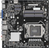
ASRock H510TM-ITX User Manual - Page 30
Step 4, Step 5, Step 6, Step 7
 |
View all ASRock H510TM-ITX manuals
Add to My Manuals
Save this manual to your list of manuals |
Page 30 highlights
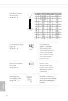
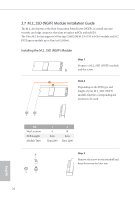
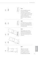
B A B A B A H510TM-ITX Step 4 Move the standoff based on the module type and length. The standoff is placed at the nut location A by default. Skip Step 4 and 5 and go straight to Step 6 if you are going to use the default nut. Otherwise, release the standoff by hand. Step 5 Peel off the yellow protective film on the nut to be used. Hand tighten the standoff into the desired nut location on the motherboard. Step 6 Align and gently insert the M.2 (NGFF) SSD module into the M.2 slot. Please be aware that the M.2 (NGFF) SSD module only fits in one orientation. English B A 20o B NUT2 NUT1 Step 7 Tighten the screw with a screwdriver to secure the module into place. Please do not overtighten the screw as this might damage the module. 25
-
 1
1 -
2
-
3
-
4
-
5
-
6
-
7
-
8
-
9
-
10
-
11
-
12
-
13
-
14
-
15
-
16
-
17
-
18
-
19
-
20
-
21
-
22
-
23
-
24
-
 25
25 -
 26
26 -
 27
27 -
 28
28 -
 29
29 -
 30
30 -
 31
31 -
 32
32 -
 33
33 -
 34
34 -
 35
35 -
36
-
37
-
38
-
39
-
40
-
41
-
42
-
43
-
44
-
45
-
46
-
47
-
48
-
49
-
50
-
51
-
52
-
53
-
54
-
55
-
56
-
57
-
58
-
59
-
60
-
61
-
62
-
63
-
64
-
65
-
66
-
67
-
68
-
69
 |
 |

H510TM-ITX
25
English
Step 4
Move the standoff based on the
module type and length.
°e standoff is placed at the nut
location A by default. Skip Step 4 and
5
and go straight to Step
6
if you are
going to use the default nut.
Otherwise, release the standoff by
hand.
B
A
Step 5
Peel off the yellow protective film on
the nut to be used. Hand tighten the
standoff into the desired nut location
on the motherboard.
A
B
A
B
20
o
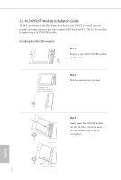
Step 6
Align and gently insert the M.2
(NGFF) SSD module into the M.2
slot.
Please be aware that the M.2
(NGFF) SSD module only fits in one
orientation.
NUT1
NUT2
B
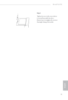
Step 7
Tighten the screw with a
screwdriver to secure the
module into place. Please do
not overtighten the screw as
this might damage the module.
B
A