ASRock X99 Extreme4 User Manual - Page 28
function. If the Ultra M.2
 |
View all ASRock X99 Extreme4 manuals
Add to My Manuals
Save this manual to your list of manuals |
Page 28 highlights
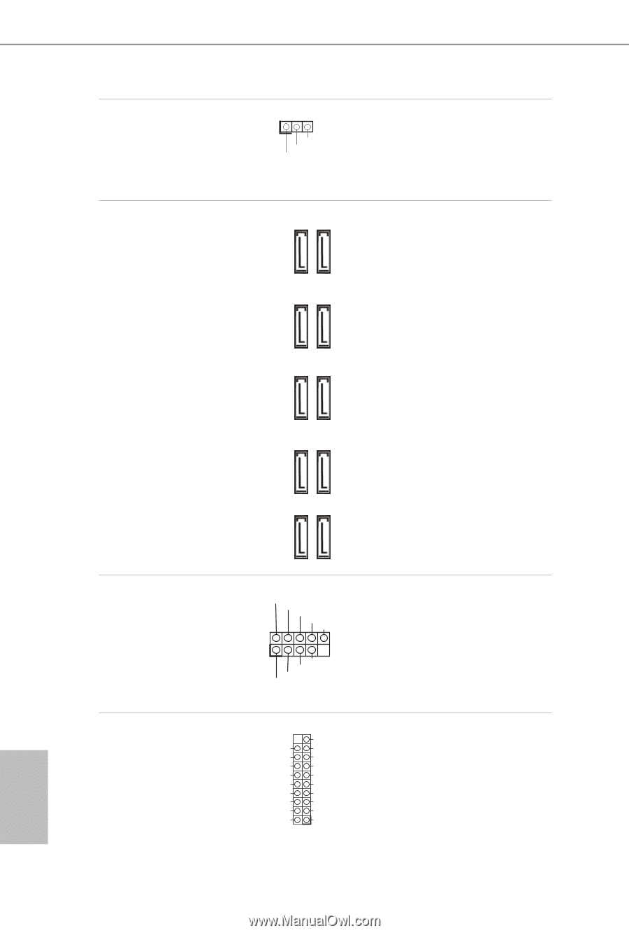
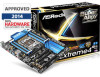
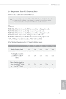
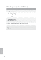
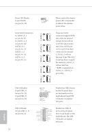
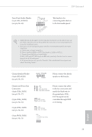
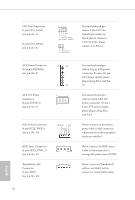
Power LED Header (3-pin PLED1) (see p.6, No. 18) Serial ATA3 Connectors (S_SATA3_0_1: see p.6, No. 11) (S_SATA3_2_3: see p.6, No. 12) (SATA3_0_1: see p.6, No. 13) (SATA3_2_3: see p.6, No. 14) (SATA3_4_5: see p.6, No. 15) SATA3_0 S_SATA3_2 S_SATA3_0 1 PLEDPLED+ PLED+ SATA3_1 S_SATA3_3 S_SATA3_1 Please connect the chassis power LED to this header to indicate the system's power status. hese ten SATA3 connectors support SATA data cables for internal storage devices with up to 6.0 Gb/s data transfer rate. If the eSATA port on the rear I/O has been connected, the internal S_SATA3_3 will not function. If the Ultra M.2 Socket has been occupied, the internal S_SATA3_2 will not function. * RAID is supported on SATA3_0 ~ SATA3_5 ports only. SATA3_5 SATA3_3 SATA3_4 SATA3_2 USB 2.0 Headers (9-pin USB4_5) (see p.6, No. 22) (9-pin USB6_7) (see p.6, No. 23) USB 3.0 Header (19-pin USB3_4_5) (see p.6, No. 9) 22 USB_PWR PP+ GND DUMMY 1 GND P+ PUSB_PWR Besides four USB 2.0 ports on the I/O panel, there are two headers on this motherboard. Each USB 2.0 header can support two ports. Vbus IntA_PA_SSRXIntA_PA_SSRX+ GND IntA_PA_SSTXIntA_PA_SSTX+ GND IntA_PA_DIntA_PA_D+ Vbus IntA_PB_SSRXIntA_PB_SSRX+ GND IntA_PB_SSTXIntA_PB_SSTX+ GND IntA_PB_DIntA_PB_D+ Dummy 1 Besides four USB 3.0 ports on the I/O panel, there is one header on this motherboard. his USB 3.0 header can support two ports. English
-
 1
1 -
2
-
3
-
4
-
5
-
6
-
7
-
8
-
9
-
10
-
11
-
12
-
13
-
14
-
15
-
16
-
17
-
18
-
19
-
20
-
21
-
22
-
 23
23 -
 24
24 -
 25
25 -
 26
26 -
 27
27 -
 28
28 -
 29
29 -
 30
30 -
 31
31 -
 32
32 -
 33
33 -
34
-
35
-
36
-
37
-
38
-
39
-
40
-
41
-
42
-
43
-
44
-
45
-
46
-
47
-
48
-
49
-
50
-
51
-
52
-
53
-
54
-
55
-
56
-
57
-
58
-
59
-
60
-
61
-
62
-
63
-
64
-
65
-
66
-
67
-
68
-
69
-
70
-
71
-
72
-
73
-
74
-
75
-
76
-
77
-
78
-
79
-
80
-
81
-
82
-
83
-
84
-
85
-
86
-
87
-
88
-
89
-
90
-
91
-
92
-
93
-
94
 |
 |