ASRock X99 Extreme4 User Manual - Page 30
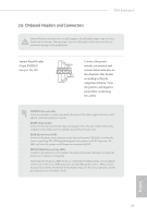
Please connect the ´DD Saver
 |
View all ASRock X99 Extreme4 manuals
Add to My Manuals
Save this manual to your list of manuals |
Page 30 highlights
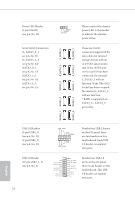
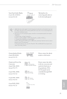
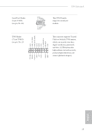
CPU Fan Connectors (4-pin CPU_FAN1) (see p.6, No. 4) (3-pin CPU_FAN2) (see p.6, No. 6) 4 3 21 GND +12V CPU_FAN_SPEED FAN_SPEED_CONTROL GND FAN_VOLTAGE CPU_FAN_SPEED his motherboard provides a 4-Pin CPU fan (Quiet Fan) connector. If you plan to connect a 3-Pin CPU fan, please connect it to Pin 1-3. ATX Power Connector (24-pin ATXPWR1) (see p.6, No. 8) ATX 12V Power Connector (8-pin ATX12V1) (see p.6, No. 3) PCIe Power Connector (4-pin PCIE_PWR1) (see p.6, No. 30) HDD Saver Connector (4-pin SATA_PWR_1) (see p.6, No. 21) hunderbolt AIC Connector (5-pin TBT1) (see p.6, No. 29) 12 24 1 13 8 5 4 1 1 his motherboard provides a 24-pin ATX power connector. To use a 20-pin ATX power supply, please plug it along Pin 1 and Pin 13. his motherboard provides an 8-pin ATX 12V power connector. To use a 4-pin ATX power supply, please plug it along Pin 1 and Pin 5. Please connect a 4 pin molex power cable to this connector when more than three graphics cards are installed. Please connect the HDD Saver Cable to this connector to manage the power state of HDD. Please connect a hunderbolt™ add-in card (AIC) to this connector via the GPIO cable. English 24
-
 1
1 -
2
-
3
-
4
-
5
-
6
-
7
-
8
-
9
-
10
-
11
-
12
-
13
-
14
-
15
-
16
-
17
-
18
-
19
-
20
-
21
-
22
-
23
-
24
-
 25
25 -
 26
26 -
 27
27 -
 28
28 -
 29
29 -
 30
30 -
 31
31 -
 32
32 -
 33
33 -
 34
34 -
 35
35 -
36
-
37
-
38
-
39
-
40
-
41
-
42
-
43
-
44
-
45
-
46
-
47
-
48
-
49
-
50
-
51
-
52
-
53
-
54
-
55
-
56
-
57
-
58
-
59
-
60
-
61
-
62
-
63
-
64
-
65
-
66
-
67
-
68
-
69
-
70
-
71
-
72
-
73
-
74
-
75
-
76
-
77
-
78
-
79
-
80
-
81
-
82
-
83
-
84
-
85
-
86
-
87
-
88
-
89
-
90
-
91
-
92
-
93
-
94
 |
 |