ASRock Z690 PG Velocita User Manual - Page 37
Warning: Please make, sure that the power cable, connected is for the CPU, and not the graphics,
 |
View all ASRock Z690 PG Velocita manuals
Add to My Manuals
Save this manual to your list of manuals |
Page 37 highlights
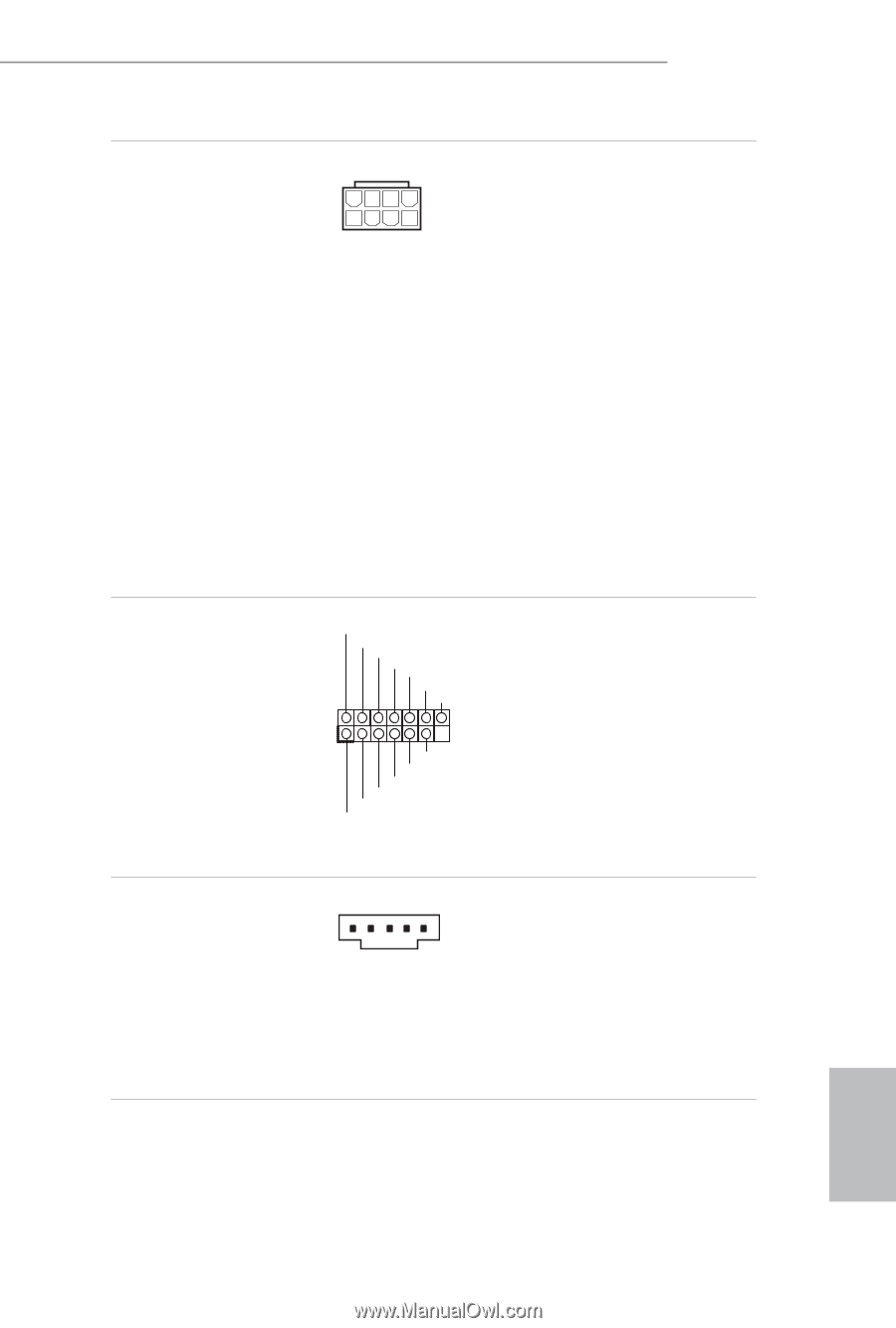
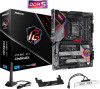
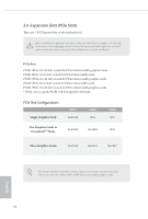
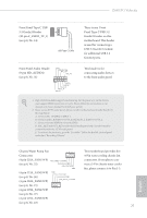
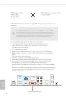
Z690 PG Velocita ATX 12V Power Connectors (8-pin ATX12V1) (see p.8, No. 1) (8-pin ATX12V2) (see p.8, No. 2) SPI TPM Header (13-pin SPI_TPM_J1) (see p.8, No. 24) Thunderbolt AIC Connector (5-pin TB1) (see p.8, No. 28) 8 5 4 1 This motherboard provides two 8-pin ATX 12V power connectors. To use a 4-pin ATX power supply, please plug it along Pin 1 and Pin 5. *Connecting an ATX 12V 8-pin cable to ATX12V2 is optional. *Warning: Please make sure that the power cable connected is for the CPU and not the graphics card. Do not plug the PCIe power cable to this connector. SPI_DQ3 SPI_PWR Dummy CLK SPI_MOSI RST# TPM_PIRQ 1 SPI_TPM_CS# GND RSMRST# SPI_MISO SPI_CS0 SPI_DQ2 This connector supports SPI Trusted Platform Module (TPM) system, which can securely store keys, digital certificates, passwords, and data. A TPM system also helps enhance network security, protects digital identities, and ensures platform integrity. 1 Please connect a Thunderbolt™ add-in card (AIC) to the Thunderbolt AIC connector via the GPIO cable. *Please install the Thunderbolt™ AIC card to PCIE3 (default slot). English 29
-
 1
1 -
2
-
3
-
4
-
5
-
6
-
7
-
8
-
9
-
10
-
11
-
12
-
13
-
14
-
15
-
16
-
17
-
18
-
19
-
20
-
21
-
22
-
23
-
24
-
25
-
26
-
27
-
28
-
29
-
30
-
31
-
 32
32 -
 33
33 -
 34
34 -
 35
35 -
 36
36 -
 37
37 -
 38
38 -
 39
39 -
 40
40 -
 41
41 -
 42
42 -
43
-
44
-
45
-
46
-
47
-
48
-
49
-
50
-
51
-
52
-
53
-
54
-
55
-
56
-
57
-
58
-
59
-
60
-
61
-
62
-
63
-
64
-
65
-
66
-
67
-
68
-
69
-
70
-
71
-
72
-
73
-
74
-
75
-
76
-
77
-
78
-
79
-
80
-
81
-
82
-
83
-
84
-
85
-
86
-
87
-
88
-
89
-
90
-
91
-
92
-
93
-
94
-
95
-
96
-
97
-
98
-
99
-
100
-
101
-
102
-
103
-
104
-
105
-
106
-
107
-
108
-
109
-
110
-
111
-
112
-
113
-
114
-
115
-
116
-
117
-
118
-
119
-
120
-
121
-
122
-
123
-
124
-
125
-
126
-
127
-
128
 |
 |