ASRock Z77 Extreme9 User Manual - Page 49
Consumer Infrared Module Header
 |
View all ASRock Z77 Extreme9 manuals
Add to My Manuals
Save this manual to your list of manuals |
Page 49 highlights
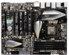
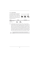
USB 2.0 Headers (9-pin USB2_3) (see p.14, No. 26) (9-pin USB4_5) (see p.14, No. 27) USB_PWR P-3 P+3 GND DUMMY 1 GND P+2 P-2 USB_PWR Besides two default USB 2.0 ports on the I/O panel, there are three USB 2.0 headers on this motherboard. Each USB 2.0 header can support two USB 2.0 ports. (9-pin USB6_7) (see p.14, No. 28) USB 3.0 Header (19-pin USB3_9_10) (see p.14, No. 10) (19-pin USB3_11_12) (see p.14, No. 9) Vbus IntA_P4_SSRXIntA_P4_SSRX+ GND IntA_P4_SSTXIntA_P4_SSTX+ GND IntA_P4_DIntA_P4_D+ Vbus IntA_P4_SSRXIntA_P4_SSRX+ GND IntA_P4_SSTXIntA_P4_SSTX+ GND IntA_P4_DIntA_P4_D+ Vbus IntA_P5_SSRXIntA_P5_SSRX+ GND IntA_P5_SSTXIntA_P5_SSTX+ GND IntA_P5_DIntA_P5_D+ DUMMY Besides eight default USB 3.0 ports on the I/O panel, there are two USB 3.0 headers on this motherboard. Each USB 3.0 header can support two USB 3.0 ports. Vbus IntA_P5_SSRXIntA_P5_SSRX+ GND IntA_P5_SSTXIntA_P5_SSTX+ GND IntA_P5_DIntA_P5_D+ DUMMY Infrared Module Header (5-pin IR1) (see p.14, No. 33) IRTX +5VSB DUMMY 1 GND IRRX This header supports an optional wireless transmitting and receiving infrared module. Consumer Infrared Module Header (4-pin CIR1) (see p.14 No. 29) 1 GND IRTX IRRX ATX+5VSB This header can be used to connect the remote controller receiver. 49
-
 1
1 -
2
-
3
-
4
-
5
-
6
-
7
-
8
-
9
-
10
-
11
-
12
-
13
-
14
-
15
-
16
-
17
-
18
-
19
-
20
-
21
-
22
-
23
-
24
-
25
-
26
-
27
-
28
-
29
-
30
-
31
-
32
-
33
-
34
-
35
-
36
-
37
-
38
-
39
-
40
-
41
-
42
-
43
-
 44
44 -
 45
45 -
 46
46 -
 47
47 -
 48
48 -
 49
49 -
 50
50 -
 51
51 -
 52
52 -
 53
53 -
 54
54 -
55
-
56
-
57
-
58
-
59
-
60
-
61
-
62
-
63
-
64
-
65
-
66
-
67
-
68
-
69
-
70
-
71
-
72
-
73
-
74
-
75
-
76
-
77
-
78
-
79
-
80
-
81
-
82
-
83
-
84
-
85
-
86
-
87
-
88
-
89
-
90
-
91
-
92
-
93
-
94
-
95
-
96
-
97
-
98
-
99
 |
 |
