| Section |
Page |
| User’s Guide |
1 |
| Adaptec CI/O Management Software |
1 |
| Adaptec CI/O Management Software |
3 |
| User’s Guide |
3 |
| Contents |
5 |
| 1 Getting Started |
5 |
| 2 Installing CI/O Software |
5 |
| 3 Entering and Viewing System Information � |
5 |
| 4 Viewing SCSI Device Information |
6 |
| 5 Configuring Arrays and Spares |
6 |
| 6 Viewing Array and Device Information |
6 |
| 7 Performing Array, Spare, and Disk Operations |
7 |
| 8 Scheduling and Monitoring Array Operations |
7 |
| 9 Setting Security Options |
7 |
| 10 Managing Arrays and Spares |
7 |
| A Configuration Settings |
8 |
| B SAF-TE Enclosure Management |
8 |
| Glossary |
8 |
| Index |
8 |
| 1 |
9 |
| Getting Started |
9 |
| Overview of Adaptec CI/O Management Software |
10 |
| Conventions |
11 |
| 2 |
13 |
| Installing CI/O Software |
13 |
| Installing Adaptec CI/O Management Software on Windows NT Server or Workstation |
15 |
| 1 Start Windows NT. |
15 |
| 2 Insert the Adaptec CI/O Management Software CD�ROM in your CD�ROM drive. |
15 |
| 3 Locate the Adaptec CI/O Management Software Setup Application: |
15 |
| 4 Double-click the Setup Application icon. The Welcome screen appears as shown in Figure Figure�2�1. |
15 |
| Figure 2�1. Welcome Screen |
15 |
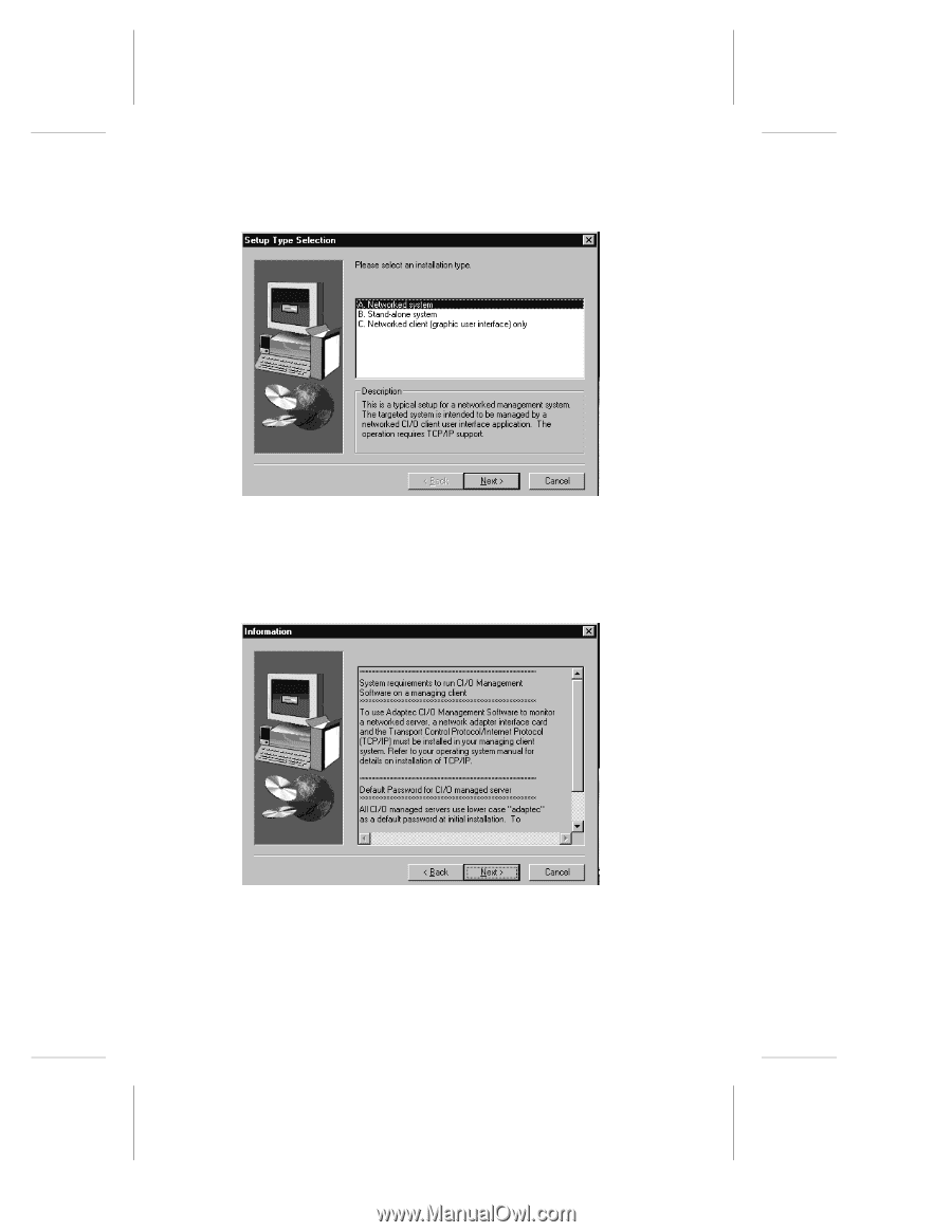
| 5 Click on Next. The Setup Type Selection screen appears. |
16 |
| Figure 2�2. Setup Type Selection Screen |
16 |
| 6 If you are setting up a Windows NT server, select Networked System and click on Next. If you ar... |
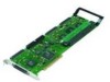
16 |
| Figure 2�3. Information Screen |
16 |
| 7 Click on Next. The Choose Destination Location screen appears. |
17 |
| Figure 2�4. Choose Destination Location Screen |
17 |
| 8 Use the Browse button to select the pathname for your installation folder or select the default... |
17 |
| Figure 2�5. Select Components Screen |
18 |
| 9 Select the components you want to install and clear the components you do not want to install. ... |
18 |
| Figure 2�6. Select Program Folder Screen |
18 |
| 10 Select the program folder from the existing folders list or type a new folder name. Click on N... |
19 |
| Figure 2�7. Start Copying Files Screen |
19 |
| 11 Click on Next to begin copying files. When the files are copied, the CI/O ReadMe file appears ... |
19 |
| Figure 2�8. CI/O ReadMe file |
19 |
| 12 Click Yes to view the ReadMe file or click No to view the Setup Complete screen as shown in Fi... |
20 |
| Figure 2�9. Setup Complete Screen |
20 |
| 13 The setup is now complete. Select Yes, I want to restart my computer now. Click on Finish. |
20 |
| 14 Wait while the system reboots. |
20 |
| 15 To start the user interface for Adaptec CI/O Management Software, go to Start > Programs > Ada... |
21 |
| Stopping CI/O Array Management Service 4.00 |
21 |
| 1 Double-click the My Computer icon. |
21 |
| 2 Double-click the Control Panel icon. |
21 |
| 3 Double-click the Services icon as shown in Figure 2�10. |
21 |
| Figure 2�10. Control Panel |
21 |
| 4 Highlight the CIO Array Management Service 4.00 and click Stop, as shown in Figure 2�11. |
21 |
| Figure 2�11. Services |
22 |
| 5 Repeat step 4 to stop NobleNet Portmapper. |
22 |
| Modifying Automatic Start of the Services |
22 |
| 1 Double-click the My Computer icon. |
22 |
| 2 Double-click the Control Panel icon. |
22 |
| 3 Double-click the Services icon. |
22 |
| 4 Highlight CIO Array Management Service 4.00 (see Figure�2�11) and double-click. The Service win... |
23 |
| Figure 2�12. Service Window |
23 |
| 5 Select Manual and click OK. |
23 |
| 6 Follow steps 4 and 5 to stop the Automatic Start for CIOArrayManagerRPC Command, CIOArrayManage... |
23 |
| Uninstalling the Adaptec CI/O Management Software in Windows |
23 |
| 1 Double-click the My Computer icon. |
23 |
| 2 Double-click the Control Panel icon. |
23 |
| 3 Double-click the Add/Remove Programs icon. |
23 |
| 4 Select Adaptec CI/O Management Software 4.00 and click Add/Remove. |
23 |
| Installing Adaptec CI/O Management Software on a Networked Windows 95/98 or NT Client |
24 |
| 1 Start Windows 95/98 or Windows NT. |
24 |
| 2 Insert the Adaptec CI/O Management Software CD�ROM in your CD�ROM drive. |
24 |
| 3 Double-click on the My Computer icon and then double-click on the CD-ROM drive icon. |
25 |
| 4 Double-click on the Setup icon. The Welcome screen appears. |
25 |
| Figure 2�13. Welcome Screen |
25 |
| 5 Click on Next. If you are running under Windows NT, the Setup Type Selection screen appears. Th... |
26 |
| Figure 2�14. Setup Type Selection Screen |
26 |
| 6 Select Networked client (user interface) only and click on Next. The Information screen appears. |
26 |
| Figure 2�15. Information Screen |
26 |
| 7 Click on Next. The Choose Destination Location screen appears. |
27 |
| Figure 2�16. Choose Destination Location Screen |
27 |
| 8 Use the Browse button to select the pathname for your installation folder or select the default... |
27 |
| Figure 2�17. Select Program Folder Screen |
27 |
| 9 Select the program folder from the existing folders list or type a new folder name. Click on Ne... |
28 |
| Figure 2�18. Start Copying Files Screen |
28 |
| 10 Click on Next to begin copying files. Once the folders are copied, the CI/O ReadMe file appear... |
28 |
| Figure 2�19. CI/O ReadMe file |
28 |
| 11 Click Yes to view the ReadMe file or click No to view the Setup Complete screen as shown in Fi... |
29 |
| Figure 2�20. Setup Complete Screen |
29 |
| 12 The setup is now complete. Select Yes, I want to restart my computer now. Click on Finish. |
29 |
| 13 To start the user interface for Adaptec CI/O Management Software, go to Start > Programs > Ada... |
29 |
| Installing the TIRPC Communications Module on NetWare Servers v4.11 and v.5.0 |
30 |
| 1 Insert the Adaptec CI/O Management Software CD�ROM in your DOS-mounted CD�ROM drive. |
30 |
| 2 Bring up the server using the following pathname: |
30 |
| 3 From the NetWare System Console prompt (:), type one of the following commands and press Enter: |
30 |
| 4 Select Product Options (for NW 5.0) or Installation Options (for NW4.11) from the Configuration... |
30 |
| 5 Select Install a Product Not Listed from the Other Installation Actions menu. |
30 |
| 6 Press <F3> key to specify your path. |
30 |
| 7 Enter the path to the CD-ROM (for example, d:\\). The CD-ROM drive must be a DOS CD-ROM drive. F... |
30 |
| 8 Select Continue and access the CD-ROM from the Select An Action menu. |
30 |
| 9 Select NetWare 4.0 TIRPC Runtime and Configuration Files and press Enter. (TIRPC must be instal... |
30 |
| 10 Press Enter to accept the default choice of sys:\\system\\. |
30 |
| 11 At the Start Installation menu, select Yes. |
30 |
| 12 At the Overwrite Existing Files menu, select Yes if you are prompted to overwrite the RPCNET.C... |
31 |
| 13 At the Installation for Select Files group done message, press Esc twice. |
31 |
| 14 At the Exit Installation screen, select Yes. |
31 |
| 15 At the next two screens, press Esc. |
31 |
| 16 At the Exit Install (for NW 4.11) or nwconfig (for NW 5.0) screen, select Yes. |
31 |
| Installing the Adaptec CI/O Management Software on Novell NetWare Servers |
31 |
| 1 Insert the Adaptec CI/O Management Software in your CD�ROM drive. Adaptec CI/O NWSETUP NLM supp... |
32 |
| 2 From the NetWare System Console prompt (:), type the following command (X is the CD-ROM drive o... |
32 |
| 3 Type the following command and press Enter: |
32 |
| 4 From the NWSETUP Select Operation menu, select Default �Installation or �Custom Installation (p... |
32 |
| 5 At the Install menu, press Enter. |
32 |
| 6 If the message “File: SYS:SYSTEM\ waspi.cdm already exists!” displays, select overwrite. |
32 |
| 7 At the end of the installation process, press Enter when you are prompted to update the autoexe... |
32 |
| 8 Press Escape to exit Install. |
32 |
| 9 Reboot the system. |
32 |
| Installing Adaptec CI/O Management Software on UnixWare 7.0.x Servers |
33 |
| Mount the CD-ROM for UnixWare v7.0.x |
33 |
| 1 Log onto UnixWare as a desktop user and open the SCO Administration Utility. |
33 |
| 2 Double-click on the File system Manager to open it. |
33 |
| 3 At the Filesystem Manager, select Mount -> Add Mount Configuration -> Local. |
33 |
| 4 At the Local Mount Configuration window |
33 |
| 5 At the Advanced Options window, locate the File Name Conversion drop-down menu and select Do No... |
33 |
| 6 When the Local Mount Configuration window appears again, select OK. |
33 |
| 7 Select OK at the next window to start mounting the file system. |
33 |
| Install the Adaptec CI/O Management Software on UnixWare v7.0.x |
34 |
| 1 At the System Administration window, double-click on Software Management. |
34 |
| 2 Double-click on Application Installer. |
34 |
| 3 At the Install From menu, select Other from the drop-down menu. |
34 |
| 4 Click on Find Folder to open the View Folder window. Click on the correct mount-point for the C... |
34 |
| 5 Click on the CIO400 directory and then click on UnixWare. Use the arrow keys to highlight the c... |
34 |
| 6 At the Application Installer Window the cio40 icon appears. Click on Install to begin the insta... |
34 |
| 7 Next, you need to remove the mount configuration. Locate the Filesystem Manager screen and sele... |
34 |
| 8 Go to the Mount drop-down menu, select Remove Mount Configuration and then click on Yes. |
34 |
| 9 You can now close the Filesystem Manger window and the Application Installer window. |
34 |
| Uninstalling the Adaptec CI/O Management Software on UnixWare v7.0.x |
35 |
| 1 In the System Administration window, double-click on Software Management. |
35 |
| 2 Double-click on Application Installer. |
35 |
| 3 In the Application Installer window, click on the cio40 directory. |
35 |
| 4 Click on the Remove button to start the uninstall process. |
35 |
| 5 You must manually remove the ciodata directory from your system. |
35 |
| 3 |
37 |
| Entering and Viewing System Information � |
37 |
| Entering and Viewing System Information |
38 |
| Starting the Program |
38 |
| 1 Start Windows. |
38 |
| 2 Double-click the icon in the Adaptec CI/O Management Software group to start the program. |
38 |
| Adding a New Server Address |
38 |
| 1 Click the button. The Add Server dialog box appears, as shown in Figure�3�1. |
39 |
| Figure 3�1. Add Server Dialog Box |
39 |
| 2 Enter the server’s IP address or name, which can be up to 32 characters. This name will appear ... |
39 |
| 3 Enter a description of the server—for example, Application Server or Video Server. This descrip... |
39 |
| 4 Click OK to add the new server information. If the server name/address is not correct, you will... |
40 |
| Viewing System Information |
41 |
| 1 Click to open the System Monitor window. Each system is represented by an icon in the top part ... |
41 |
| 2 Click the Detail View icon to display detailed information about the system in the top part of ... |
42 |
| 3 Click the Icon View icon to display only the system icon. |
42 |
| Reconnecting to a Server |
42 |
| 1 Click to open the System Monitor window. |
42 |
| 2 Highlight the server you need to reconnect. |
42 |
| 3 Click on the System Monitor window toolbar. |
42 |
| Deleting a Server Address |
43 |
| 1 Click to open the System Monitor window. |
43 |
| 2 Right-click the icon of the server you want to delete and select Delete from the drop-down menu... |
43 |
| 3 At the prompt, click Yes to confirm the deletion of the currently selected server. |
43 |
| Viewing a List of Current System Events |
43 |
| 1 Click to open the System Monitor window. Event notifications appear in the bottom part of this ... |
44 |
| Figure 3�2. Ssytem Monitor Window |
44 |
| 2 View the event information for one or all systems. New entries appear on the list as the system... |
44 |
| 3 To view detailed information about an event, Doubleclick the list entry. The Event Detail dialo... |
45 |
| Figure 3�3. Event Detail Dialog Box |
45 |
| 4 Click Close when you are finished viewing the Event Detail dialog box. When you do this, you au... |
45 |
| 5 Click the Filter button on the System Monitor window toolbar to filter the event notifications ... |
46 |
| 6 Click the Save As button to save the event list to a file. |
46 |
| 7 Close the System Monitor window when you are finished viewing the events, or leave it open so y... |
46 |
| Entering and Viewing Preference Information |
46 |
| Changing Filter Options |
46 |
| 1 Click to open the Preferences dialog box. |
46 |
| 2 Click the Filter tab. The Filter dialog box appears, as shown in Figure�3�4. |
47 |
| Figure 3�4. Filter Dialog Box |
47 |
| 3 Select or deselect the check boxes to control which kinds of messages appear in the System Moni... |
47 |
| 4 Click OK to record the Filter option changes. |
47 |
| Selecting Notification Settings |
48 |
| 1 Click to open the Preferences dialog box. |
48 |
| 2 Click the Notification tab; the Notification dialog box appears, as shown in Figure�3�5. |
48 |
| Figure 3�5. Event Notification Dialog Box |
48 |
| 3 Select or deselect the check boxes to control how you will be notified of event notifications r... |
48 |
| 4 Select the defaults or click OK to save these settings. |
49 |
| Configuring Email |
49 |
| Figure 3�6. Connection Setting Dialog Box |
49 |
| 1 In the Internet Connection Settings you can select a Direct connection (non-modem) or a Dial-up... |
49 |
| 2 Complete the Identity section with the correct email address, Outgoing mail (SMTP) server (opti... |
49 |
| 3 Click on the Recipient List tab to display the Recipient dialog box as shown in Figure 3�7. |
50 |
| Figure 3�7. Recipient List Dialog Box |
50 |
| 4 In this dialog box you can add, modify, or remove recipients. If you select Add, the Add Recipi... |
50 |
| Figure 3�8. Add Recipient Dialog Box |
50 |
| 5 Enter the following information in the Add Recipient dialog box. |
50 |
| 6 Click OK. |
51 |
| Viewing Historical Information |
51 |
| 1 Click to open the Historic Event Log for the currently selected system, as shown in Figure�3�9. |
52 |
| Figure 3�9. Historic Log Window |
52 |
| 2 View the historical event information for the system. New entries are added to the top of the l... |
52 |
| 3 To view detailed information about an entry on the list, double-click the entry. The Event Deta... |
52 |
| 4 Click Close when you are finished viewing the Event Detail dialog box. |
52 |
| 5 Click to change the Filter options. |
52 |
| 6 Close the window when you are finished viewing log entries, or minimize it as an icon on the sc... |
53 |
| Interpreting and Responding to Event Messages |
53 |
| Additional Preference Information |
54 |
| 1 Click to open the Preferences dialog box, as shown in Figure�3�10. |
54 |
| Figure 3�10. Preferences Dialog Box - Ping Tab |
54 |
| 2 Specify a Ping interval. This is the interval at which the management client will verify contin... |
54 |
| 3 Click the Notification tab to change the way in which you are alerted of event notifications re... |
54 |
| 4 Click the Filter tab to view the Filter dialog box. Select or deselect the check boxes, to filt... |
55 |
| 5 Click the Password tab to display the Password dialog box, as shown in Figure�3�11. |
55 |
| Figure 3�11. Password Dialog Box |
55 |
| 6 Select a Password Time-out option to set the level of password protection for this workstation ... |
55 |
| 7 Click the Launch tab to display the Launch dialog box, as shown in Figure�3�12. |
56 |
| Figure 3�12. Launch Dialog Box |
56 |
| 8 Select how you want to initially view your application. You can start Adaptec CI/O Management S... |
56 |
| 9 Click OK to change the option information or to close the dialog box. |
56 |
| 4 |
57 |
| Viewing SCSI Device Information |
57 |
| Viewing SCSI Devices |
58 |
| Figure 4�1. Physical Resources Window - Graphical View |
58 |
| Figure 4�2. Physical Resources Window - Detailed View |
59 |
| 1 Click to open the Storage Configuration window. |
59 |
| 2 Right-click the icon of the device and select Information from the drop-down menu. The icons ar... |
59 |
| Viewing the SCSI Information Dialog Box |
60 |
| Figure 4�3. SCSI Information Dialog Box - Description |
60 |
| Figure 4�4. SCSI Information Dialog Box - Status |
61 |
| Viewing SCSI Adapter and Array Controller Information |
62 |
| Figure 4�5. Controller Information Dialog box - Description Tab |
62 |
| Figure 4�6. Controller Information Dialog Box - Capabilities Tab |
63 |
| Viewing SCSI Channel Information |
64 |
| Figure 4�7. Channel Information Dialog Box |
64 |
| Rescanning the SCSI Adapters and Array Controllers |
65 |
| Differences in Rescan Between SCSI Adapters and Array Controllers |
65 |
| Rescan Details |
65 |
| Managing SCSI Adapters |
66 |
| 5 |
69 |
| Configuring Arrays and Spares |
69 |
| Creating an Array |
70 |
| 1 Click to open the Storage Configuration window. All array and spare configuration tasks are don... |
70 |
| Figure 5�1. Configuration - Graphical View |
71 |
| Figure 5�2. Configuration - Detailed View |
71 |
| 2 Before you start defining the new array, decide what RAID level you want to use, how many disks... |
71 |
| 3 Click the Create New Array button on the Storage Configuration window toolbar. The Create Array... |
72 |
| Figure 5�3. Create Array - Members Dialog Box |
72 |
| 4 Highlight the controller from the Select a Controller window. All array disks must be connected... |
73 |
| 5 Select disks for the new array by highlighting the disk in the Available drives window and clic... |
73 |
| 6 When all disks for the new array have been selected click Next. The Create Array - Name and Typ... |
74 |
| Figure 5�4. Create Array - Name and Type Dialog Box |
74 |
| 7 Type a name for the new array. The name can be up to 15 characters, including spaces and any ot... |
74 |
| 8 Highlight the desired RAID type for the array in the Select array type window. The bar graphs o... |
74 |
| 9 Click Next. The Create Array - Advanced dialog box appears, as shown in Figure�5�5. |
75 |
| Figure 5�5. Create Array - Advanced Dialog Box |
75 |
| 10 Select dedicated spares if desired. The disks in the list are the available disks you did not ... |
75 |
| 11 Select Cache Enabled to enable cache for the array. If the cache-enabled checkbox is greyed ou... |
75 |
| 12 The assigned checkbox indicates the total number of blocks available for caching. |
75 |
| 13 Select the desired optimization option from the Optimize Performance drop-down list. Refer to ... |
76 |
| 14 Deselect auto-initialize to create the array now but initialize it at a later time. You can do... |
76 |
| 15 Select the desired stripe size from the Stripe size drop-down list. |
76 |
| 16 Click Finish. The array will be initialized at this point, unless you deselected auto�initiali... |
76 |
| 17 An event notification is generated when the initialization process starts. An icon for the new... |
76 |
| 18 When initialization is complete, exit from Adaptec CI/O Management Software and reboot the sys... |
77 |
| Making an Array the First Virtual Device |
77 |
| 1 Click to open the Storage Configuration window. |
77 |
| 2 Click the icon in the Logical Resources window for the array that you want to make bootable. |
78 |
| 3 Right-click and select Make first virtual device from the drop- down menu. |
78 |
| 4 At the prompt, confirm that you want to make this array the boot device. |
78 |
| 5 Close all applications on the system containing the array. If the selected array does not alrea... |
78 |
| 6 Install the operating system on the array. See your array controller’s Hardware and Installatio... |
78 |
| 7 Make sure that you restart CI/O after you reboot the server. |
78 |
| Deleting an Array |
78 |
| 1 Click to open the Storage Configuration window. |
78 |
| 2 Click the icon in the Logical Resources window for the array you want to delete. |
78 |
| 3 Right-click and select Delete from the drop-down menu or press the Delete key. A warning appear... |
78 |
| 4 When the confirmation message appears, confirm that you want to delete the array. |
79 |
| Initializing an Array |
79 |
| 1 Click to open the Storage Configuration window. |
80 |
| 2 Click the icon of the array you want to initialize. |
80 |
| 3 Right-click and select Initialize from the drop-down menu. (This option is greyed out if the ar... |
80 |
| 4 When the confirmation message appears, click Yes to confirm that you want to initialize the array. |
80 |
| Creating Dedicated Spares or a Spare Pool |
82 |
| 1 Click to open the Storage Configuration window. |
82 |
| 2 Click to display the Create Spare dialog box, as shown in Figure�5�6. |
83 |
| Figure 5�6. Create Spare Dialog Box |
83 |
| 3 Select the Adapter from the Adapter list box. |
83 |
| 4 If you want to dedicate the spare to a specific array, select Dedicated in the Spare type field... |
83 |
| 5 Click OK to save your changes. |
84 |
| 6 Click Yes at the prompt to confirm creation of the spare. |
84 |
| 7 Select the disk you wish to use as a spare from the Select drive window. |
84 |
| Deleting a Spare |
85 |
| 1 Click to open the Storage Configuration window. |
85 |
| 2 Right-click the icon of the spare you want to delete and select Delete from the drop-down menu.... |
85 |
| 3 At the prompt, click Yes to confirm that you want to delete the spare. |
85 |
| 6 |
87 |
| Viewing Array and Device Information |
87 |
| 1 Click to begin the Adaptec CI/O Management software. |
88 |
| 2 Click to open the Storage Configuration window. |
88 |
| 3 Right-click the icon that represents the device for which you want to view information and sele... |
88 |
| Figure 6�1. Storage Configuration Window Icons |
88 |
| Viewing Array Information |
89 |
| Figure 6�2. Array Information Dialog Box - Description Tab |
89 |
| Figure 6�3. Array Information Dialog Box - Status Tab |
90 |
| Viewing Spare Information |
91 |
| Figure 6�4. Spare Information Dialog Box |
91 |
| Viewing SCSI Device Information from an Array Controller |
92 |
| Rescanning the Server |
92 |
| 1 Click to open the Storage Configuration window. |
93 |
| 2 Click on the Storage Configuration window toolbar. |
93 |
| 3 At the prompt, confirm that you want to rescan the server. When the rescan is complete, any har... |
93 |
| Viewing Array Controller Information |
94 |
| Figure 6�5. Controller Information Dialog Box - Description Tab |
94 |
| Figure 6�6. Controller Information Dialog Box - Capabilities Tab |
95 |
| Viewing Channel Information |
96 |
| Figure 6�7. Channel Information Dialog Box |
96 |
| 7 |
99 |
| Performing Array, Spare, and Disk Operations |
99 |
| Performing Array Operations |
100 |
| 1 Click to open the Storage Configuration window. |
100 |
| 2 Right-click the icon that represents the array , spare , or SCSI disk you want to work on. |
100 |
| 3 Select the operation you want to perform. See the appropriate section of this chapter for a des... |
100 |
| Reconstructing an Array |
100 |
| 1 Determine which array is in Critical status and which disk in the array has failed. |
101 |
| 2 If the array enclosure does not support hot swapping, pause I/O to the array before you continu... |
101 |
| 3 Remove the failed disk and allow I/O to resume. |
101 |
| 4 Insert a good disk of at least the same storage capacity. Be sure that the SCSI ID of the new d... |
101 |
| 5 Issue a Rescan command to detect the new disk. |
101 |
| 6 If you installed a new disk (or disks), make the disk into a spare by following the directions ... |
101 |
| 7 Click to open the Storage Configuration window. Right- click on the Array icon that looks like ... |
102 |
| 8 Enter the required information for the Reconstruct operation in the Scheduler dialog box. You c... |
102 |
| 9 Select an Execution Priority - high, medium, or low. |
102 |
| 10 Click OK. |
102 |
| 11 At the prompt, confirm that you want to reconstruct the array member. |
102 |
| 12 Read the event notifications that appear in the System Monitor window (they may also appear as... |
102 |
| Pausing I/O on an Array |
103 |
| 1 Click to open the Storage Configuration window. |
103 |
| 2 Right-click the icon of the array you want to pause and select Pause I/O on the drop-down menu. |
103 |
| 3 When the Pause I/O dialog box appears, enter a pause interval that does not exceed the maximum ... |
103 |
| 4 Complete your work with the array disks. Data I/O resumes automatically at the end of the pause... |
104 |
| Verifying Array Integrity |
104 |
| 1 Click to open the Storage Configuration window. |
104 |
| 2 Right-click on the Array icon. |
104 |
| 3 Select Verify from the drop-down menu. |
104 |
| 4 Leave the autocorrect box checked so that any data parity or mirroring mismatches will be corre... |
104 |
| 5 Select OK if you want to verify parity immediately, or select Scheduled if you want to schedule... |
105 |
| 6 If you select Scheduled, enter a start time, start day of the week, and other information. (See... |
105 |
| 7 Select an Execution Priority - high, medium, or low. This sets the system resources devoted to ... |
105 |
| 8 Click OK to start the operation (if you selected Immediate) or to enter it on the list of sched... |
105 |
| 9 At the prompt, click Yes to confirm that you want to verify parity information. |
105 |
| Blinking Array Drive Lights |
105 |
| 1 Click to open the Storage Configuration window. |
105 |
| 2 Right-click on an Array icon in the Logical Resources area. |
105 |
| 3 Select Blink from the drop-down menu. |
105 |
| 4 Look at the array enclosure to see which disks are members of the array. |
105 |
| 5 Click OK to the drive lights from blinking. |
106 |
| 6 You can also click on the Stop blinking lights icon to stop all of the drive lights from blinking. |
106 |
| Reactivating an Off-line Array |
106 |
| 1 Click to open the Storage Configuration window. |
106 |
| 2 Right-click on the dimmed icon of the off-line array and select Reactivate from the drop-down l... |
106 |
| 3 At the prompt, confirm that you want to reactivate the array. Be sure that any hardware problem... |
106 |
| Changing an Array Name |
106 |
| 1 Click to open the Storage Configuration window. |
106 |
| 2 Right-click the icon of the array whose name you want to change. |
106 |
| 3 Select Rename from the drop-down menu.The Change Name dialog box appears. |
107 |
| 4 Type the new array name and click OK. |
107 |
| 5 At the prompt, confirm that you want to change the array name. This change appears immediately ... |
107 |
| Forcing a Spare |
107 |
| 1 Be sure that one or more spares are available for the array. These can either be dedicated spar... |
107 |
| 2 Click to open the Storage Configuration window. |
107 |
| 3 Right-click on the icon of the array with the suspect disk and select Force a spare from the dr... |
107 |
| 4 Select the disk that you want to replace. |
107 |
| 5 Click OK to replace this disk with a spare. |
107 |
| 6 At the prompt, confirm that you want to replace the disk with the spare. |
107 |
| Performing Spare Operations |
108 |
| Testing All Spares |
108 |
| 1 Click to open the Storage Configuration window. |
108 |
| 2 Right-click the icon of any spare in the Logical Resources window and select Test All Spares fr... |
108 |
| 3 Select OK if you want to test all spares immediately, or select Scheduled if you want to schedu... |
109 |
| 4 If you select Scheduled, enter a starting time, starting day, and other information. |
109 |
| 5 Click OK to start the operation (if you selected Immediate) or to enter it on the list of sched... |
109 |
| 6 At the prompt, confirm that you want to test the spares. |
109 |
| 7 When the test is complete the results will be viewable as an event. (The message is also record... |
109 |
| 8 Replace the failed disk immediately with a good disk of at least the same capacity. |
109 |
| Blinking the Spare Drive Light |
109 |
| 1 Click to open the Storage Configuration window. |
109 |
| 2 Right-click the spare icon in Logical Resources window and select Blink in the drop-down menu. |
109 |
| 3 Look at the array enclosure to see which disk light is blinking. |
109 |
| 4 Click OK to stop all the drive light from blinking. |
109 |
| 5 You can also click to stop the drive lights from blinking. |
109 |
| Performing Disk Operations |
110 |
| Blinking the Drive Light |
110 |
| 1 Click to open the Storage Configuration window. |
110 |
| 2 Right-click a drive icon in the left side of the window and select Blink from the drop-down menu. |
110 |
| 3 Look at the array enclosure to see which drive light is blinking. |
110 |
| 4 Click OK to stop the drive light from blinking. |
110 |
| 5 You can also click on to stop all of the drive lights from blinking. |
110 |
| Downing the Drive |
111 |
| 1 Click to open the Storage Configuration window. |
111 |
| 2 Right-click the icon of the disk you want to down and select Down a Drive from the drop-down me... |
111 |
| 3 Wait until the Reconstruct operation is completed, and then continue with your work in the prog... |
111 |
| Pausing I/O to an Array Disk Drive |
111 |
| 1 Click to open the Storage Configuration window. |
112 |
| 2 Right-click the icon of the disk you want to pause and select Pause I/O from the drop-down menu. |
112 |
| 3 When the Pause I/O dialog box appears, enter a pause interval that does not exceed the maximum ... |
112 |
| 4 Complete your work before the pause period expires. I/O resumes automatically at the end of thi... |
112 |
| 8 |
113 |
| Scheduling and Monitoring Array Operations |
113 |
| Setting Scheduling Options |
114 |
| 1 Define a new scheduled operation: Reconstruct an Array, Verify Integrity of Array, or Test All ... |
114 |
| Figure 8�1. Scheduler Dialog Box |
114 |
| 2 Select Immediate to perform the action immediately or Scheduled to schedule it for later. |
114 |
| 3 If you select Scheduled, select Once, Periodically, Daily, or Weekly. Enter other information s... |
115 |
| 4 Click OK to record the scheduling options. You may be prompted to confirm the activity. |
115 |
| Viewing and Managing Scheduled Activities |
116 |
| 1 Click on the main toolbar to open the Activity View window, as shown in Figure�8�2. |
116 |
| Figure 8�2. Activity View Window |
116 |
| 2 Information about each activity is shown in the window. Each kind of activity has a unique icon... |
116 |
| 3 To change the priority of a Verify or Reconstruct operation that is currently running (as indic... |
117 |
| 4 To delete an activity that is not currently running, right-click its icon and select Delete fro... |
117 |
| 5 To abort a currently-running activity, select its icon and click the Abort button . After you c... |
117 |
| 9 |
119 |
| Setting Security Options |
119 |
| Changing the Password |
120 |
| 1 Click to open the System Monitor window. Then select the icon of the server whose password you ... |
120 |
| 2 Right-click on the system you wish to change the password for and select Change Password. The S... |
120 |
| Figure 9�1. Set Access Password Dialog Box |
120 |
| 3 Type the new password in the New Password field. |
120 |
| 4 Type the new password again in the Confirm Password field. |
121 |
| 5 Click OK to accept the new password. |
121 |
| Setting Password Time-out Options |
121 |
| 1 Click to open the Preferences dialog box and click the Password tab to display the Password dia... |
121 |
| Figure 9�2. Password Dialog Box |
121 |
| 2 Select one of the three Password time-out options. Here is a description of the options: |
121 |
| 3 Click Defaults to accept the default settings or click OK to accept the password time-out change. |
122 |
| Controlling Guest Access |
123 |
| 1 Click the Reconnect icon in the System Monitor widow. |
123 |
| 2 Enter the password when prompted. |
123 |
| 1 Click to open the System Monitor window. |
123 |
| 2 Right-click the server icon whose guest access setting you want to change and select Guest Access. |
124 |
| 3 When the Enable/Disable Guest Access dialog box appears, select or deselect the Enable Guest Ac... |
124 |
| 4 Click OK to enter the change. Enter the password when you are prompted to do so. The Guest Acce... |
124 |
| 10 |
125 |
| Managing Arrays and Spares |
125 |
| Responding to a Critical Array |
126 |
| 1 Click the Array icon and observe the Disk icons of the array members on the left side of the sc... |
127 |
| 2 Right-click the icon and then select Blink from the drop-down menu to blink the drive light on ... |
127 |
| 3 Observe which drive light is blinking. This is the disk that you need to replace. If no lights ... |
127 |
| a The disk is still connected but has failed so badly that it cannot respond to the Blink command... |
127 |
| b The disk has been removed or its power cord or SCSI cable has been disconnected. |
127 |
| c The disk does not have an LED that indicates I/O activity. |
127 |
| 4 If the array enclosure supports hot swapping, remove the failed drive. |
127 |
| 5 Insert the replacement drive and issue the Rescan command. |
128 |
| 6 If the array enclosure does not support hot swapping, pause I/O to the array before you continu... |
128 |
| 7 Remove the failed disk drive and allow I/O to resume. |
128 |
| 8 Pause I/O again. |
128 |
| 9 Insert the replacement drive and allow I/O to resume. |
128 |
| 10 Select the icon of the new disk, and issue a Create Spare command. |
128 |
| 11 When a Pool spare with a capacity as large as the smallest member of the critical array or a s... |
128 |
| Replacing a Spare |
128 |
| 1 Delete the spare. (See Deleting a Spare on page�5�17.) |
128 |
| 2 If the spare is in an enclosure that supports hot swapping, remove the spare disk drive and rep... |
129 |
| 3 If the spare is not in an enclosure that supports hot swapping, pause I/O (see Pausing I/O to a... |
129 |
| 4 Remove the spare and allow I/O to resume. |
129 |
| 5 Pause I/O again, insert the replacement drive, and allow I/O to resume. |
129 |
| 6 Use Adaptec CI/O Management Software to mark the new disk drive as a dedicated spare or a pool ... |
129 |
| 1 If the array enclosure supports hot swapping, remove the spare that is marked as down. |
129 |
| 2 Insert the replacement drive and issue the Rescan command. |
129 |
| 3 If the spare is in an enclosure that does not support hot swapping, pause I/O. (Skip this step ... |
129 |
| 4 Remove the spare and allow I/O to resume. |
129 |
| 5 Pause I/O again. |
129 |
| 6 Insert the replacement drive and allow I/O to resume. |
129 |
| 7 Use Adaptec CI/O Management Software to mark the new disk drive as a dedicated spare or a pool ... |
129 |
| Replacing an Active Array Member |
130 |
| 1 Perform a Down operation on the array member you want to replace (see Downing the Drive on page... |
130 |
| 2 If the array enclosure supports hot swapping, remove the member marked as down. |
130 |
| 3 Insert the replacement drive and issue the rescan command. |
130 |
| 4 If the array member is an enclosure that does not support hot swapping, pause I/O. (Skip steps ... |
130 |
| 5 Remove the disk drive and allow I/O to resume. |
130 |
| 6 Pause I/O again. |
130 |
| 7 Insert the replacement drive and allow I/O to resume. |
130 |
| 8 When a pool spare with a capacity as large as the smallest member of the critical array or a sp... |
130 |
| Responding to an Off-line Array |
130 |
| Notes on Replacing Disk Drives |
132 |
| Optimizing Array Performance |
133 |
| 1 Click to open the Storage Configuration window. |
133 |
| 2 Right-click on the Array icon and select Optimize Performance from the drop-down menu. The Opti... |
133 |
| Figure 10�1. Optimize Performance Dialog Box |
133 |
| 3 A list of Optimized Applications will appear. Each entry is prefaced by the word workstation or... |
133 |
| 4 Select the desired entry from the list. All applications optimized by this setting will appear ... |
134 |
| 5 Select Caching enabled to enable caching on this array. When you enable caching, Adaptec CI/O M... |
134 |
| 6 Click the Edit button. The Performance Setting dialog box appears, as shown in Figure�10�2. |
134 |
| Figure 10�2. Performance Setting Dialog Box |
134 |
| 7 To create a new setting, enter a new name for the performance setting in the Optimize Performan... |
134 |
| 8 Click the Use as default checkbox if you want to use this setting as the default when creating ... |
134 |
| 9 Select the desired Read and Write Caching settings. (See Read Caching on page�10�11 and Write C... |
134 |
| 10 Click Save to save the new performance setting. The changes are not written to disk until you ... |
135 |
| 11 When the Optimize Performance dialog box displays, click OK to save your changes. |
135 |
| Read Caching |
135 |
| Write Caching |
136 |
| Other Performance Tips |
137 |
| Selecting a RAID Level for an Array |
138 |
| A |
141 |
| Configuration Settings |
141 |
| I/O Manager Settings |
142 |
| [ASPIMODEL] DisableASPI = [Yes | No] |
142 |
| [ASPIMODEL] DisableASPI = [Yes | No] |
142 |
| LoadSavedConfiguration= [Yes| No] |
142 |
| DiscoveryInterval = n |
142 |
| PollInterval = n |
142 |
| StatisticsInterval = n |
143 |
| TapeBusyTolerationTime = n |
143 |
| Lun0Required = [Yes | No] |
143 |
| Lun0Only = [Yes | No] |
143 |
| ErrorInstrumentation = [Yes | No] |
143 |
| IOInstrumentation = [Yes | No] |
144 |
| ResetInstrumentationOnPowerup = [Yes | No] |
144 |
| ResetInstrumentationOnDiscovery = [Yes | No] |
144 |
| SMARTPolling = [Yes | No] |
144 |
| SMARTTest = [Yes | No | testcount] |
144 |
| ForceHAWide16 = [Yes | No] ForceHAWide32 = [Yes | No] |
145 |
| AccessibleDrivers = [* | comma delimited list of driver names] |
146 |
| [ARRAYOPERATIONS] |
147 |
| RecreatePriority= |
147 |
| VerifyIfDirty= |
147 |
| [SYSTEM] |
147 |
| PauseEnabled= |
147 |
| ServerLogSizeInMegabytes= |
147 |
| StatisticsCollectionInterval= |
148 |
| WarnAfterFirstPFAEvent= |
148 |
| [TASKS] |
148 |
| TestAllSpares= |
148 |
| [CAPABILITIES] |
148 |
| EnableRAID5= |
148 |
| EnableRAID10= |
149 |
| [ENCLOSUREMANAGER] |
149 |
| EnabledEnclosureInterfaces=SAF-TE |
149 |
| SAF-TEPollingPeriodInSeconds=5 |
149 |
| B |
151 |
| SAF-TE Enclosure Management |
151 |
| Viewing Enclosure Information |
152 |
| 1 Click to enter the Storage Configuration window. |
152 |
| 2 Right-click the icon of the enclosure you wish to view and select Information from the drop-dow... |
152 |
| Figure B�1. Enclosure Information Dialog Box |
152 |
| Viewing Subsystem Status Details |
154 |
| Figure B�2. Component Status Dialog Box |
154 |
| Temperature Sensors |
154 |
| Fans |
155 |
| Power Supplies |
155 |
| Identification of Events |
156 |
| Events for SAF-TE Enclosures |
156 |
| 1 Enclosure found [ SAF-TE : unique address]— Posted for each found and successfully initialized ... |
156 |
| 2 Enclosure not responding [ SAF-TE : unique address]— Posted for each unrecoverable error that o... |
156 |
| 3 Enclosure removed from bus [ SAF-TE : unique address]— Posted when an enclosure device is remov... |
156 |
| 4 Device id=SCSI_ID slot#=slot_ number inserted [ SAF-TE : unique address]— When a device is inse... |
156 |
| 5 Device id=SCSI_ID slot#=slot_number removed [ SAF-TE : unique address]— Posted when a device is... |
156 |
| 6 For each change in the status of a cooling fan or temperature, the following events indicating ... |
157 |
| a Fan #fan_number is malfunctioning [ SAF-TE : unique address] |
157 |
| b Fan #fan_number is removed [ SAF-TE : unique address] |
157 |
| c Fan #fan_number is in an unknown state [ SAF-TE : unique address] |
157 |
| d Temperature is out of normal range, sensor #sensor_number [ SAF-TE : unique address] |
157 |
| e Overall Temperature is out of normal range [ SAF-TE : unique address] |
157 |
| f Fan #fan_number is operational [ SAF-TE : unique address] |
157 |
| g Overall temperature is in normal range [ SAF-TE : unique address] |
157 |
| 7 For each change in the status of the power supplies connected to the enclosure, the following e... |
158 |
| a PowerSupply #power_supply is operational and OFF [SAF-TE unique address] |
158 |
| b PowerSupply #power_supply is operational and ON [SAF-TE unique address] |
158 |
| c PowerSupply #power_supply is malfunctioning and OFF [SAF-TE unique address] |
158 |
| d PowerSupply #power_supply is malfunctioning but ON [SAF-TE unique address] |
158 |
| e PowerSupply #power_supply is present [SAF-TE unique address] |
158 |
| f PowerSupply #power_supply is not present[SAF-TE unique address] |
158 |
| g PowerSupply #power_supply is in unknown state[SAF-TE unique address] |
158 |
| 8 For each change in the status of the door lock of the enclosure, the following events indicatin... |
158 |
| a Door is locked [SAF-TE unique address] |
158 |
| b Door is unlocked [SAF-TE unique address] |
158 |
| c Speaker is present [SAF-TE unique address] |
158 |
| d Speaker is not present [SAF-TE unique address] |
158 |
| 9 CI/O will set LED states of devices located inside enclosures in the following cases: |
158 |
| Events for Devices Connected to RAID Boards |
159 |
| Glossary |
161 |
| Using the Glossary |
161 |
| adapter, array |
161 |
| adapter, I/O |
161 |
| agent |
161 |
| array |
161 |
| array resources |
161 |
| auto-initialize |
161 |
| availability |
161 |
| blink |
162 |
| bootable array |
162 |
| bridge controller |
162 |
| bus |
162 |
| CI/O |
162 |
| cache |
162 |
| capacity |
162 |
| channel |
162 |
| clustering |
162 |
| compatible container |
162 |
| controller, storage |
163 |
| dedicated spare |
163 |
| device slot |
163 |
| discovery |
163 |
| disk |
163 |
| disk ID |
163 |
| DMI |
163 |
| enclosure |
163 |
| enclosure ID |
163 |
| enclosure management device |
163 |
| event log |
164 |
| event notifications settings |
164 |
| expand |
164 |
| failover |
164 |
| fault tolerant |
164 |
| fault tolerant arrays |
164 |
| file system |
164 |
| first virtual device |
164 |
| forcing a spare |
164 |
| hot-swap |
165 |
| initialized array |
165 |
| legacy disk |
165 |
| Logical Unit Number |
165 |
| low-level format |
165 |
| logical device |
165 |
| LUN |
165 |
| metadata |
165 |
| MIB |
165 |
| MIF |
166 |
| mirroring; mirrored array |
166 |
| monitoring |
166 |
| offline array |
166 |
| offset |
166 |
| online capacity expansion |
166 |
| parity |
166 |
| password time-out options |
166 |
| pause I/O |
166 |
| physical resources |
166 |
| physical view |
167 |
| poll |
167 |
| pool of spares |
167 |
| RAID |
167 |
| RAID-0 |
167 |
| RAID-1 (mirrored) |
167 |
| RAID 0/1 (mirrored) |
167 |
| RAID-5 |
167 |
| reconstruction |
167 |
| redundancy |
167 |
| referential integrity |
168 |
| replication |
168 |
| rescan |
168 |
| RPC |
168 |
| SAF-TE |
168 |
| scalability |
168 |
| SCSI Device ID |
168 |
| SCSI ID |
168 |
| Simple Network Management Protocol (SNMP) |
168 |
| slot |
168 |
| S.M.A.R.T |
169 |
| spare pool |
169 |
| stand-alone disk |
169 |
| stripe set |
169 |
| stripe set of mirror sets |
169 |
| stripe size |
169 |
| striping, disk; striped array |
169 |
| subsystem |
169 |
| target ID |
169 |
| task |
169 |
| verify |
170 |
| virtual device |
170 |
| virtual device order |
170 |
| volume |
170 |
| volume set |
170 |
| warning threshold temperature |
170 |
| zero |
170 |
| Index |
171 |
| A |
171 |
| B |
171 |
| C |
171 |
| D |
171 |
| E |
171 |
| F |
172 |
| G |
172 |
| H |
172 |
| I |
172 |
| M |
172 |
| O |
172 |
| P |
172 |
| R |
172 |
| S |
172 |
| T |
173 |
 1
1 11
11 12
12 13
13 14
14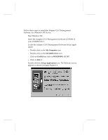 15
15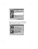 16
16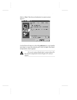 17
17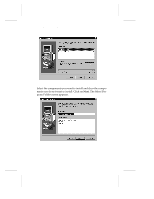 18
18 19
19 20
20 21
21