Adaptec 2400A Installation Guide - Page 83
Adaptec SCSI RAID 3400S
 |
View all Adaptec 2400A manuals
Add to My Manuals
Save this manual to your list of manuals |
Page 83 highlights
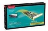
Card and Module Diagrams Adaptec SCSI RAID 3400S P4 P6 J10 J11 IRQ 8 7 6 5 4 3 2 1 ECCERR Audible Alarm ECCEN J14 J7 P3 P9 J8 J2 TRMEN-B TRMENHD-A TRMEN-A TRMP WR -B TRMP WR -A J12 J1 J15 PCI Connector Part ECCEN ECCERR IRQ, 8..1 J1 J2 J12 P3 P1 P4 P6 P9 TRMEN-A/B TRMENHD-A TRMPWR-A/B Description ECC enabled LED (green) ECC error LED (red) Adapter activity LEDs Cache memory socket 1. (During operation, this socket must contain a memory module.) Cache memory socket 2. (Memory is optional for this socket.) Battery module connector Pins 1-2 Retry PCI connector Pins 1-2 NVRAM reset Pins 3-4 Reserved-do not use Hard drive activity LED connector. (Pin 1 is nearest the top edge of board.) Flash Mode 0 Termination-enabled status LED Upper 8-bit termination status LED for Channel A Termination power status LED A-5
-
 1
1 -
2
-
3
-
4
-
5
-
6
-
7
-
8
-
9
-
10
-
11
-
12
-
13
-
14
-
15
-
16
-
17
-
18
-
19
-
20
-
21
-
22
-
23
-
24
-
25
-
26
-
27
-
28
-
29
-
30
-
31
-
32
-
33
-
34
-
35
-
36
-
37
-
38
-
39
-
40
-
41
-
42
-
43
-
44
-
45
-
46
-
47
-
48
-
49
-
50
-
51
-
52
-
53
-
54
-
55
-
56
-
57
-
58
-
59
-
60
-
61
-
62
-
63
-
64
-
65
-
66
-
67
-
68
-
69
-
70
-
71
-
72
-
73
-
74
-
75
-
76
-
77
-
 78
78 -
 79
79 -
 80
80 -
 81
81 -
 82
82 -
 83
83 -
 84
84 -
 85
85 -
 86
86 -
 87
87 -
 88
88 -
89
-
90
-
91
-
92
-
93
-
94
-
95
-
96
-
97
-
98
-
99
-
100
 |
 |
