Adaptec FC2101CDR2-AC Installation Guide - Page 48
RAID Controller Circuit Boards, with the controller and ethernet boards mounted to
 |
UPC - 760884144909
View all Adaptec FC2101CDR2-AC manuals
Add to My Manuals
Save this manual to your list of manuals |
Page 48 highlights
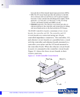
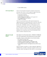
48 host and device fibre channel input/output processors (IOPs). • I/O: The I/O circuit board provides the interface to the disk drive enclosure (device) and host as well as general support functions. It also contains the switching power supply, which generates +3.3 Vdc and +2.5 Vdc from +5 Vdc, hot-swap circuits, and battery backup unit (BBU) circuits. • Ethernet (optional): The ethernet circuit board provides an ethernet interface to the controller, and connections for debug and out-of-band service to the host and device PCI busses. The RAID Controller requires a minimum of two circuit boards: the controller and I/O. The controller and I/O circuit boards are connected using two 38-pin controlled impedance connectors. The controller, I/O, and ethernet circuit boards are assembled into a stack with the controller and ethernet boards mounted to a controller cover plate and the I/O board mounted to the controller board. When the ethernet circuit board is used, it is mounted to the controller circuit board. Figure 4-1 shows the three circuit boards in their relative positions. Figure 4-1 RAID Controller Circuit Boards 2Gb SANbloc Series RAID Controller Introduction
-
 1
1 -
2
-
3
-
4
-
5
-
6
-
7
-
8
-
9
-
10
-
11
-
12
-
13
-
14
-
15
-
16
-
17
-
18
-
19
-
20
-
21
-
22
-
23
-
24
-
25
-
26
-
27
-
28
-
29
-
30
-
31
-
32
-
33
-
34
-
35
-
36
-
37
-
38
-
39
-
40
-
41
-
42
-
 43
43 -
 44
44 -
 45
45 -
 46
46 -
 47
47 -
 48
48 -
 49
49 -
 50
50 -
 51
51 -
 52
52 -
 53
53 -
54
-
55
-
56
-
57
-
58
-
59
-
60
-
61
-
62
-
63
-
64
-
65
-
66
-
67
-
68
-
69
-
70
-
71
-
72
-
73
-
74
-
75
-
76
-
77
-
78
-
79
-
80
-
81
-
82
-
83
-
84
-
85
-
86
-
87
-
88
-
89
-
90
-
91
-
92
-
93
-
94
-
95
-
96
-
97
-
98
-
99
-
100
-
101
-
102
-
103
-
104
-
105
-
106
-
107
-
108
-
109
-
110
 |
 |
